
Page 109 - Mathematical Techniques of Fractional Order Systems
P. 109
Fractional Order System Chapter | 3 97
fractional order process transfer function. Correspondingly, also the lcd of
the powers in the resulting fractional order controller transfer function
obtained from (3.62) via (3.3) will be the same.
3.7.1 Example 4
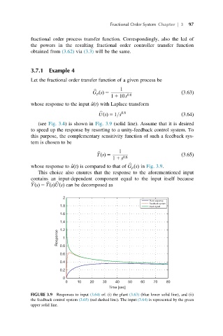
Let the fractional order transfer function of a given process be
1
G p ðsÞ 5 ð3:63Þ
b
1 1 10s 0:8
whose response to the input ^ uðtÞ with Laplace transform
UðsÞ 5 1=s 0:8 ð3:64Þ
b
(see Fig. 3.4) is shown in Fig. 3.9 (solid line). Assume that it is desired
to speed up the response by resorting to a unity-feedback control system. To
this purpose, the complementary sensitivity function of such a feedback sys-
tem is chosen to be
1
TðsÞ 5 ð3:65Þ
b
1 1 s 0:8
whose response to ^ uðtÞ is compared to that of G p ðsÞ in Fig. 3.9.
b
This choice also ensures that the response to the aforementioned input
contains an input-dependent component equal to the input itself because
YðsÞ 5 TðsÞUðsÞ can be decomposed as
b
b
b
2
Plant response
Feedback system
1.8 Input signal
1.6
1.4
Response 1.2 1
0.8
0.6
0.4
0.2
0
0 10 20 30 40 50 60 70 80
Time [sec]
FIGURE 3.9 Responses to input (3.64) of: (i) the plant (3.63) (blue lower solid line), and (ii)
the feedback control system (3.65) (red dashed line). The input (3.64) is represented by the green
upper solid line.