Page 451 - Mathematical Techniques of Fractional Order Systems
P. 451
436  Mathematical Techniques of Fractional Order Systems


            14.7.2 Permanent Magnet Synchronous Motor
            Generalization of the integer model of PMSM to the fractional order domain
            was discussed by Chun-Lai et al. (2012). The dimensionless form of the sys-
            tem is given by (Chun-Lai et al., 2012):
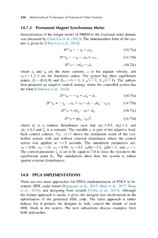
                                    D i d 52 i d 1 ωi q ;            ð14:72aÞ
                                     α 1
                                  D i q 52 i q 2 ωi d 1 γω;         ð14:72bÞ
                                   α 2
                                    D ω 5 σði q 2 ωÞ;                ð14:72cÞ
                                      α 3
            where i d and i q are the stator currents, ω is the angular velocity, and
            α i ; i 5 1; 2; 3 are the fractional orders. The system has three equilibrium
                                                p ffiffiffiffiffiffiffiffiffiffiffi  p ffiffiffiffiffiffiffiffiffiffiffi
            points: E 1 5 ð0; 0; 0Þ and E 2;3 5 ðγ 2 1; 6  γ 2 1; 6  γ 2 1Þ. The authors
            then proposed an adaptive control strategy where the controlled system has
            the form (Chun-Lai et al., 2012):
                                  D i d 52 i d 1 ωi q 2 d 1 ;        ð14:73aÞ
                                   α 1
                          D i q 52 i q 2 ωi d 1 γω 1 d 2 2 ρði q 2 i q Þ;  ð14:73bÞ
                            α 2

                                  D ω 5 σði q 2 ωÞ 1 d 3 ;           ð14:73cÞ
                                    α 3
                                                  2
                                    D ρ 5 ηði q 2i q Þ ;            ð14:73dÞ
                                      α j

            where d i is a random disturbance such that jd 1 j # 0:5, jd 2 j # 1, and

            jd 3 j # 0:3and i is a constant. The variable ρ is part of the adaptive feed-
                         d
            back control scheme. Fig. 14.15 shows the simulation result of the con-
            trolled system with and without external disturbance where the control
            action was applied at t 5 5 seconds. The simulation parameters are:
            α 1 5 0:98, α 2 5 1:0, α 3 5 0:99, α j 5 0:5, i d ð0Þ 5 2:5, i q ð0Þ 5 3, and ω 5 1.

            The control parameter i is set to be equal to 7.0 to force the system to the
                                q
            equilibrium point E 2 . The simulations show how the system is robust
            against external disturbances.

            14.8 FPGA IMPLEMENTATIONS
            There are two main approaches for FPGA implementation of FOCS in lit-
            erature: HDL coder-based (Rajagopal et al., 2017; Shah et al., 2017; Rana
            et al., 2016), and designing from scratch (Tolba et al., 2017). Although
            the former approach is easier, it gives the designer less involvement in the
            optimization of the generated HDL code. The latter approach is rather
            tedious but it permits the designer to fully control the details of each
            HDL block in the system. The next subsections discuss examples from
            both approaches.

