
Page 170 - Mechanical design of microresonators _ modeling and applications
P. 170
0-07-145538-8_CH04_169_08/30/05
Microbridges: Lumped-Parameter Modeling and Design
Microbridges: Lumped-Parameter Modeling and Design 169
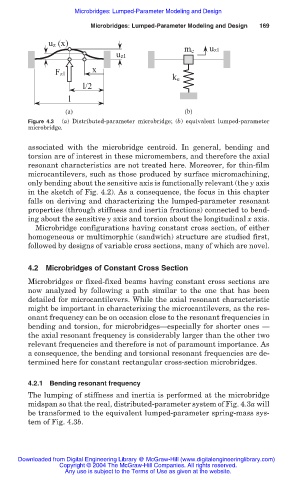
uz (x)
m e uz1
uz1
x
Fz1
k e
l/2
l
(a) (b)
Figure 4.3 (a) Distributed-parameter microbridge; (b) equivalent lumped-parameter
microbridge.
associated with the microbridge centroid. In general, bending and
torsion are of interest in these micromembers, and therefore the axial
resonant characteristics are not treated here. Moreover, for thin-film
microcantilevers, such as those produced by surface micromachining,
only bending about the sensitive axis is functionally relevant (the y axis
in the sketch of Fig. 4.2). As a consequence, the focus in this chapter
falls on deriving and characterizing the lumped-parameter resonant
properties (through stiffness and inertia fractions) connected to bend-
ing about the sensitive y axis and torsion about the longitudinal x axis.
Microbridge configurations having constant cross section, of either
homogeneous or multimorphic (sandwich) structure are studied first,
followed by designs of variable cross sections, many of which are novel.
4.2 Microbridges of Constant Cross Section
Microbridges or fixed-fixed beams having constant cross sections are
now analyzed by following a path similar to the one that has been
detailed for microcantilevers. While the axial resonant characteristic
might be important in characterizing the microcantilevers, as the res-
onant frequency can be on occasion close to the resonant frequencies in
bending and torsion, for microbridges–especially for shorter ones –
the axial resonant frequency is considerably larger than the other two
relevant frequencies and therefore is not of paramount importance. As
a consequence, the bending and torsional resonant frequencies are de-
termined here for constant rectangular cross-section microbridges.
4.2.1 Bending resonant frequency
The lumping of stiffness and inertia is performed at the microbridge
midspan so that the real, distributed-parameter system of Fig. 4.3a will
be transformed to the equivalent lumped-parameter spring-mass sys-
tem of Fig. 4.3b.
Downloaded from Digital Engineering Library @ McGraw-Hill (www.digitalengineeringlibrary.com)
Copyright © 2004 The McGraw-Hill Companies. All rights reserved.
Any use is subject to the Terms of Use as given at the website.