
Page 175 - Mechanical design of microresonators _ modeling and applications
P. 175
0-07-145538-8_CH04_174_08/30/05
Microbridges: Lumped-Parameter Modeling and Design
174 Chapter Four
H WE > @
A
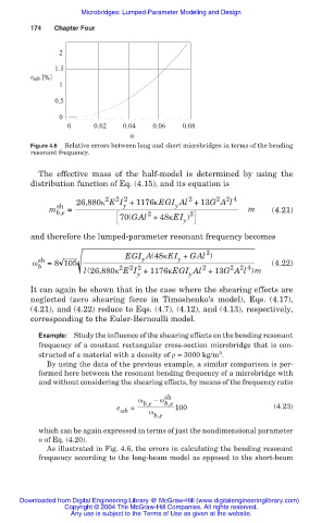
Figure 4.6 Relative errors between long and short microbridges in terms of the bending
resonant frequency.
The effective mass of the half-model is determined by using the
distribution function of Eq. (4.15), and its equation is
2
2 2 4
2 2
2
26,880ț E I + 1176țEGI Al +13G A l
y
y
sh
m b,e = m (4.21)
2
70(GAl +48țEI ) 2
y
and therefore the lumped-parameter resonant frequency becomes
2
EGI A(48țEI + GAl )
y
y
Ȧ sh =8 105 (4.22)
b
2
2 2 4
2
2 2
l(26,880ț E I +1176țEGI Al +13G A l )m
y
y
It can again be shown that in the case where the shearing effects are
neglected (zero shearing force in Timoshenko’s model), Eqs. (4.17),
(4.21), and (4.22) reduce to Eqs. (4.7), (4.12), and (4.13), respectively,
corresponding to the Euler-Bernoulli model.
Example: Study the influence of the shearing effects on the bending resonant
frequency of a constant rectangular cross-section microbridge that is con-
3
structed of a material with a density of ȡ = 3000 kg/m .
By using the data of the previous example, a similar comparison is per-
formed here between the resonant bending frequency of a microbridge with
and without considering the shearing effects, by means of the frequency ratio
Ȧ b,e Ȧ sh
b,e
e = 100 (4.23)
Ȧb Ȧ
b,e
which can be again expressed in terms of just the nondimensional parameter
Į of Eq. (4.20).
As illustrated in Fig. 4.6, the errors in calculating the bending resonant
frequency according to the long-beam model as opposed to the short-beam
Downloaded from Digital Engineering Library @ McGraw-Hill (www.digitalengineeringlibrary.com)
Copyright © 2004 The McGraw-Hill Companies. All rights reserved.
Any use is subject to the Terms of Use as given at the website.