Page 174 - Mechanical design of microresonators _ modeling and applications
P. 174

0-07-145538-8_CH04_173_08/30/05


                                          Microbridges: Lumped-Parameter Modeling and Design

                                               Microbridges: Lumped-Parameter Modeling and Design  173
                                      2

                                     1.5
                                      1
                              e kb  [%]
                                     0.5
                                      0
                                        0   0.01  0.02  0.03  0.04  0.05
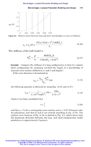
                              Figure 4.5  Relative errors between long and short microbridges in terms of stiffness.

                                                           /
                                                      Fl ț (GA) + l 2 /  (48EI )
                                                                          y
                                          u = u (0) =            2                       (4.16)
                                            z
                                                z
                              The stiffness of the half-model is
                                               sh   F        96EGI A
                                                                   y
                                              k b,e  =  =              2                 (4.17)
                                                    u
                                                     1   l(48țEI + GAl )
                                                                y
                                Example: Compare the stiffness of a long configuration to that of a similar
                                short configuration  by analyzing  one-half  the length  of a microbridge of
                                constant cross section (defined by w and t) and length l.
                                  If the error function is formulated as

                                                               sh
                                                         k b,e  – k b,e
                                                   e   =         100                      (4.18)
                                                    kb     k
                                                            b,e
                                the following equation is obtained by using Eqs. (4.13) and (4.17):
                                                       1             100Į
                                            e  =              100 =
                                             kb       2      2            2               (4.19)
                                                 1+ Gl /(4țEt )     0.12 + Į
                                where it has been considered that

                                                             t
                                                         Į =                              (4.20)
                                                             l
                                and that ț = ൣ (for a rectangular cross section) and Í = 0.25 (Poisson’s ratio
                                for polysilicon) and that E and G are related according to Eq. (2.70). The
                                relative error function of Eq. (4.19) is plotted in Fig. 4.5, which shows that
                                the maximum deviation between the long- and short-configuration model
                                predictions is approximately 2 percent.


                           Downloaded from Digital Engineering Library @ McGraw-Hill (www.digitalengineeringlibrary.com)
                                      Copyright © 2004 The McGraw-Hill Companies. All rights reserved.
                                        Any use is subject to the Terms of Use as given at the website.
   169   170   171   172   173   174   175   176   177   178   179