
Page 179 - Mechanical design of microresonators _ modeling and applications
P. 179
0-07-145538-8_CH04_178_08/30/05
Microbridges: Lumped-Parameter Modeling and Design
178 Chapter Four
600
10000
r ω
0
10
10
c 1
c w
50
50 50
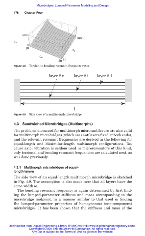
Figure 4.8 Torsion-to-bending resonant frequency ratio.
layer # n layer # i layer # 1
l
Figure 4.9 Side view of a multimorph microbridge.
4.3 Sandwiched Microbridges (Multimorphs)
The problems discussed for multimorph microcantilevers are also valid
for multimorph microbridges (which are cantilevers fixed at both ends),
and the relevant resonant frequencies are derived in the following for
equal-length and dissimilar-length multimorph configurations. Be-
cause axial vibration is seldom used in microresonators of this kind,
only torsional and bending resonant frequencies are calculated next, as
was done previously.
4.3.1 Multimorph microbridges of equal-
length layers
The side view of an equal-length multimorph microbridge is sketched
in Fig. 4.9. The assumption is also made here that all layers have the
same width w.
The bending resonant frequency is again determined by first find-
ing the lumped-parameter stiffness and mass corresponding to the
microbridge midpoint, in a manner similar to that used in finding
the lumped-parameter properties of homogeneous (one-component)
microbridges. It has been shown that the stiffness and mass of the
Downloaded from Digital Engineering Library @ McGraw-Hill (www.digitalengineeringlibrary.com)
Copyright © 2004 The McGraw-Hill Companies. All rights reserved.
Any use is subject to the Terms of Use as given at the website.