
Page 183 - Mechanical design of microresonators _ modeling and applications
P. 183
0-07-145538-8_CH04_182_08/30/05
Microbridges: Lumped-Parameter Modeling and Design
182 Chapter Four
patch 1p
tp
substrate 11
t1
l
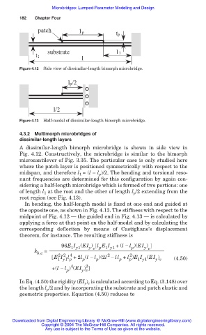
Figure 4.12 Side view of dissimilar-length bimorph microbridge.
lp/2
l/2
Figure 4.13 Half-model of dissimilar-length bimorph microbridge.
4.3.2 Multimorph microbridges of
dissimilar-length layers
A dissimilar-length bimorph microbridge is shown in side view in
Fig. 4.12. Constructively, the microbridge is similar to the bimorph
microcantilever of Fig. 3.35. The particular case is only studied here
where the patch layer is positioned symmetrically with respect to the
midspan, and therefore l 1 = (l — l p )/2. The bending and torsional reso-
nant frequencies are determined for this configuration by again con-
sidering a half-length microbridge which is formed of two portions: one
of length l 1 at the root and the other of length l p /2 extending from the
root region (see Fig. 4.13).
In bending, the half-length model is fixed at one end and guided at
the opposite one, as shown in Fig. 4.13. The stiffness with respect to the
midpoint of Fig. 4.12 – the guided end in Fig. 4.13 – is calculated by
applying a force at that point on the half-model and by calculating the
corresponding deflection by means of Castigliano’s displacement
theorem, for instance. The resulting stiffness is
96E I (EI ) l E I + (l í l )(EI )
p
1 y1
y e p 1 y1
y e
k =
b,e 2 2 4 2 2
E I l +2l (l í l )(2l í ll + l )E I (EI ) (4.50)
1 y1 p p p p p 1 y1 y e
4
+(l í l ) (EI ) 2
y e
p
In Eq. (4.50) the rigidity (EI y ) e is calculated according to Eq. (3.148) over
the length l p /2 and by incorporating the substrate and patch elastic and
geometric properties. Equation (4.50) reduces to
Downloaded from Digital Engineering Library @ McGraw-Hill (www.digitalengineeringlibrary.com)
Copyright © 2004 The McGraw-Hill Companies. All rights reserved.
Any use is subject to the Terms of Use as given at the website.