
Page 186 - Mechanical design of microresonators _ modeling and applications
P. 186
0-07-145538-8_CH04_185_08/30/05
Microbridges: Lumped-Parameter Modeling and Design
Microbridges: Lumped-Parameter Modeling and Design 185
y
symmetry line
3 2 1
x
l
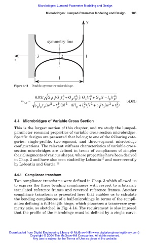
Figure 4.14 Double-symmetry microhinge.
3
3
3
p p /
6.93t 1 G t (G t + G t ) G lt + G (l í l )t 3 p
p
1 1
1 1
1 1
p
Ȧ t,e = (4.63)
2
2
2
2
2
2
2
p /
ȡ l t (w + t )(3l í 3ll + l ) l + ȡ lt (w + t )
p p p p p 1 1 1
4.4 Microbridges of Variable Cross Section
This is the largest section of this chapter, and we study the lumped-
parameter resonant properties of variable-cross-section microbridges.
Specific designs are presented that belong to one of the following cate-
gories: single-profile, two-segment, and three-segment microbridge
configurations. The relevant stiffness characteristics of variable-cross-
section microbridges are defined in terms of compliances of simpler
(basic) segments of various shapes, whose properties have been derived
17
in Chap. 2 and have also been studied by Lobontiu and more recently
by Lobontiu and Garcia. 18
4.4.1 Compliance transform
Two compliance transforms were defined in Chap. 3 which allowed us
to express the three bending compliances with respect to arbitrarily
translated reference frames and reversed reference frames. Another
compliance transform is presented here that enables us to calculate
the bending compliances of a half-microhinge in terms of the compli-
ances defining a full-length hinge, which possesses a transverse sym-
metry axis, as sketched in Fig. 4.14. The requirement is also imposed
that the profile of the microhinge must be defined by a single curve.
Downloaded from Digital Engineering Library @ McGraw-Hill (www.digitalengineeringlibrary.com)
Copyright © 2004 The McGraw-Hill Companies. All rights reserved.
Any use is subject to the Terms of Use as given at the website.