
Page 171 - Mechanical design of microresonators _ modeling and applications
P. 171
0-07-145538-8_CH04_170_08/30/05
Microbridges: Lumped-Parameter Modeling and Design
170 Chapter Four
1 0
l/2
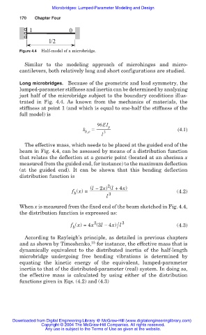
Figure 4.4 Half-model of a microbridge.
Similar to the modeling approach of microhinges and micro-
cantilevers, both relatively long and short configurations are studied.
Long microbridges. Because of the geometric and load symmetry, the
lumped-parameter stiffness and inertia can be determined by analyzing
just half of the microbridge subject to the boundary conditions illus-
trated in Fig. 4.4. As known from the mechanics of materials, the
stiffness at point 1 (and which is equal to one-half the stiffness of the
full model) is
96EI y
k b,e = (4.1)
l 3
The effective mass, which needs to be placed at the guided end of the
beam in Fig. 4.4, can be assessed by means of a distribution function
that relates the deflection at a generic point (located at an abscissa x
measured from the guided end, for instance) to the maximum deflection
(at the guided end). It can be shown that this bending deflection
distribution function is
2
(l ಥ 2x) (l +4x)
f (x) = (4.2)
b
l 3
When x is measured from the fixed end of the beam sketched in Fig. 4.4,
the distribution function is expressed as:
2
/
f (x) =4x (3l 4x) l 3 (4.3)
b
According to Rayleigh’s principle, as detailed in previous chapters
15
and as shown by Timoshenko, for instance, the effective mass that is
dynamically equivalent to the distributed inertia of the half-length
microbridge undergoing free bending vibrations is determined by
equating the kinetic energy of the equivalent, lumped-parameter
inertia to that of the distributed-parameter (real) system. In doing so,
the effective mass is calculated by using either of the distribution
functions given in Eqs. (4.2) and (4.3)
Downloaded from Digital Engineering Library @ McGraw-Hill (www.digitalengineeringlibrary.com)
Copyright © 2004 The McGraw-Hill Companies. All rights reserved.
Any use is subject to the Terms of Use as given at the website.