Page 214 - Mechanical design of microresonators _ modeling and applications
P. 214

0-07-145538-8_CH04_213_08/30/05


                                          Microbridges: Lumped-Parameter Modeling and Design

                                               Microbridges: Lumped-Parameter Modeling and Design  213
                                                                    y


                                          l1        l2        l1
                                        α                      α
                                 w1                                   w1

                                                    w2                     fixed
                              x              w            w

                                                               x
                               fixed                   x
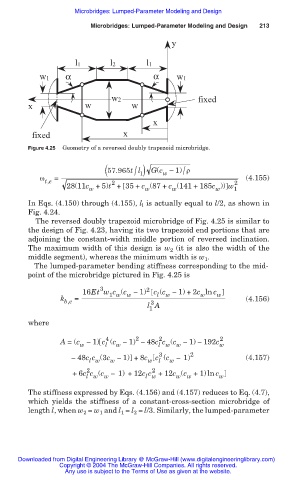
                              Figure 4.25  Geometry of a reversed doubly trapezoid microbridge.

                                                          / 1)
                                                                       /
                                                  ( 57.965t l  G(c í 1) ȡ
                                                                  w
                                 Ȧ   =                                                  (4.155)
                                  t,e               2                                2
                                        28(11c +5)t + 35 + c (87 + c (141 + 185c )) w
                                              w              w      w           w    1
                              In Eqs. (4.150) through (4.155), l  is actually equal to l/2, as shown in
                                                            l
                              Fig. 4.24.
                                The reversed doubly trapezoid microbridge of Fig. 4.25 is similar to
                              the design of Fig. 4.23, having its two trapezoid end portions that are
                              adjoining the constant-width middle portion of reversed inclination.
                              The maximum width of this design is w  (it is also the width of the
                                                                    2
                              middle segment), whereas the minimum width is w .
                                                                             1
                                The lumped-parameter bending stiffness corresponding to the mid-
                              point of the microbridge pictured in Fig. 4.25 is
                                                 3            2
                                            16Et w c (c Ì 1) c (c Ì 1) +2c ln c w
                                                                l
                                                    1 w
                                                        w
                                                                            w
                                                                   w
                                       k b,e  =                                         (4.156)
                                                               3
                                                              l A
                                                              1
                              where
                                                           2
                                                   4
                                                                 2
                                       A = (c Ì 1) c (c Ì 1) Ì 48c c (c Ì 1) Ì 192c 2
                                                                 l w
                                                                                 w
                                                   l
                                                                      w
                                                     w
                                            w
                                                                 3
                                         Ì 48c c (3c Ì 1) +8c w  c (c Ì 1) 2            (4.157)
                                                                 l
                                                                    w
                                                    w
                                              l w
                                                               2
                                              2
                                          +6c c (c Ì 1) +12c c +12c (c +1) ln c  w
                                                                      w
                                                                        w
                                                             l w
                                             l w
                                                  w
                              The stiffness expressed by Eqs. (4.156) and (4.157) reduces to Eq. (4.7),
                              which  yields the  stiffness of a constant-cross-section microbridge of
                              length l, when w 2  = w 1  and l 1  = l 2  = l/3. Similarly, the lumped-parameter
                           Downloaded from Digital Engineering Library @ McGraw-Hill (www.digitalengineeringlibrary.com)
                                      Copyright © 2004 The McGraw-Hill Companies. All rights reserved.
                                        Any use is subject to the Terms of Use as given at the website.
   209   210   211   212   213   214   215   216   217   218   219