Page 218 - Mechanical design of microresonators _ modeling and applications
P. 218

0-07-145538-8_CH04_217_08/30/05


                                          Microbridges: Lumped-Parameter Modeling and Design

                                               Microbridges: Lumped-Parameter Modeling and Design  217
                                                                z


                                t1


                                           l1           l1
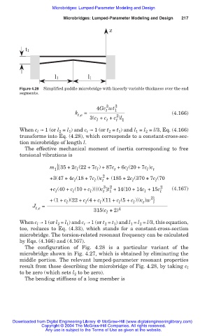
                              Figure 4.28  Simplified paddle microbridge with linearly variable thickness over the end
                              segments.

                                                               3
                                                           4Gc wt 1 3
                                                               t
                                                   k   =                                (4.166)
                                                    t,e            2
                                                         3(c + c + c )l 1
                                                               t
                                                                   t
                                                           l
                              When c ඎ 1 (or l  = l ) and c ඎ 1 (or t  = t ) and l  = l  = l/3, Eq. (4.166)
                                     l
                                                                2
                                             2
                                                                          1
                                                        t
                                                                    1
                                                                              2
                                                 1
                              transforms into Eq. (4.28), which corresponds to a constant-cross-sec-
                              tion microbridge of length l.
                                The effective mechanical moment of inertia  corresponding  to free
                              torsional vibrations is
                                         m { 35 + 2c (22 + 7c ) +87c +6c (20 + 7c )c
                                           1        l       l     t    l       l  t
                                                              2
                                         +3(47 + 4c (18 + 7c ))c + (185 + 2c (370 + 7c (70
                                                                         l
                                                           l
                                                              t
                                                                                  l
                                                   l
                                                              3 2                   2
                                         +c (40 + c (10 + c )))))c t +14(10 + 14c +15c l  (4.167)
                                                                1
                                            l
                                                              t
                                                         l
                                                  l
                                                                              l
                                         + (1+ c )(22 + c (4+ c )(11 + c (5+ c )))c )w }
                                                                                2
                                                                    l
                                                                             t
                                                                         l
                                                l
                                                       l
                                                             l
                                   J  =
                                    t,e                   315(c +2) 4
                                                               l
                              When c l ඎ 1 (or l 2  = l 1 ) and c t ඎ 1 (or t 2  = t 1 ) and l 1  = l 2  = l/3, this equation,
                              too, reduces to Eq. (4.33), which  stands for  a  constant-cross-section
                              microbridge. The torsion-related resonant frequency can be calculated
                              by Eqs. (4.166) and (4.167).
                                The configuration of  Fig. 4.28 is  a  particular  variant of the
                              microbridge shown in Fig. 4.27, which is obtained by eliminating the
                              middle portion. The relevant  lumped-parameter resonant properties
                              result from those describing the microbridge of Fig. 4.28, by taking c l
                              to be zero (which sets l 2  to be zero).
                                The bending stiffness of a long member is
                           Downloaded from Digital Engineering Library @ McGraw-Hill (www.digitalengineeringlibrary.com)
                                      Copyright © 2004 The McGraw-Hill Companies. All rights reserved.
                                        Any use is subject to the Terms of Use as given at the website.
   213   214   215   216   217   218   219   220   221   222   223