
Page 220 - Mechanical design of microresonators _ modeling and applications
P. 220
0-07-145538-8_CH04_219_08/30/05
Microbridges: Lumped-Parameter Modeling and Design
Microbridges: Lumped-Parameter Modeling and Design 219
1.6
2
r k b
1
1.001 ct
c1
2 0.5
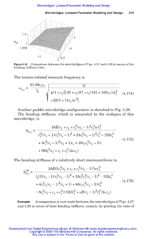
Figure 4.30 Comparison between the microbridges of Figs. 4.27 and 4.29 by means of the
bending stiffness ratio.
The torsion-related resonant frequency is
81.98c t G
t 1
Ȧ =
t,e l 2
1 ˮ(1+ c ){ 35 + c (87 + c (141 + 185c )) t 1 (4.174)
t
t
t
t
2
+28(5+11c )w }
t
Another paddle microbridge configuration is sketched in Fig. 4.29.
The bending stiffness, which is associated to the midspan of this
microbridge, is
3 3
2
16E(c + c + c )(c Ì 1) c wt 1 3
t
t
t
t
l
k b,e =
2
2 2
3
2
4
l (c Ì 1)(c (c Ì 1) +24c (c Ì 1) c Ì 192c 4
1 t l t l t t t
(4.175)
2
3
3
+4c (c Ì 1) (c +1)c +48c c (c Ì 3))
l t t t l t t
3 2
+96k (c + c + c ) ln c t
t
t
t
l
The bending stiffness of a relatively short microcantilever is
2
3
3
16EGc (c + c + c )(c í 1) wt 1 3
t
t
t
l
t
k sh =
b,e 4 2 2 2 2 4
l G(c í 1)(c (c í 1) +24c c (c í 1) í 192c
1 t l t l t t t
(4.176)
2
3
3
+4c c (c í 1) (c +1) +48c c (c í 3))l 2
l t t t l t t 1
3
2
2 2
2
í 8c (c + c + c )(12Gl + țE(c í 1) t ) ln c
t l t t 1 t 1 t
Example: A comparison is now made between the microbridges of Figs. 4.27
and 4.29 in terms of their bending stiffness, namely, by plotting the ratio of
Downloaded from Digital Engineering Library @ McGraw-Hill (www.digitalengineeringlibrary.com)
Copyright © 2004 The McGraw-Hill Companies. All rights reserved.
Any use is subject to the Terms of Use as given at the website.