
Page 225 - Mechanical design of microresonators _ modeling and applications
P. 225
0-07-145538-8_CH04_224_08/30/05
Microbridges: Lumped-Parameter Modeling and Design
224 Chapter Four
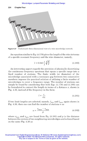
Figure 4.37 Underneath three-dimensional view of a wire microbridge network.
An equation similar to Eq. (4.179) gives the length of the wire in terms
of a specific resonant frequency and the wire diameter, namely,
t 4 E
l =0.943 ȡ (4.180)
f
An interesting aspect regards the precision of physically discretizing
the continuous frequency spectrum that spans a specific range into a
fixed number of stations. The finite width (or diameter) of the
microbridge associated with a necessary gap between two consecutive
members imposes the practical solution of utilizing a finite number of
microbridges to cover a frequency range. The number of stations can
simply be found by considering that both Eqs. (4.179) and (4.180) can
be formulated to connect the length in terms of a distance x, shown in
Fig. 4.36, instead of the frequency in the form:
c
l = (4.181)
x
If two limit lengths are selected, namely, l min and l max , again shown in
Fig. 4.36, then one can find the number of stations n as
x max Ì x min
n = (4.182)
p
where x max and x min are found from Eq. (4.181) and p is the distance
between the centers of two neighboring microbridges and is found based
on the same Fig. 4.36 as
Downloaded from Digital Engineering Library @ McGraw-Hill (www.digitalengineeringlibrary.com)
Copyright © 2004 The McGraw-Hill Companies. All rights reserved.
Any use is subject to the Terms of Use as given at the website.