
Page 222 - Mechanical design of microresonators _ modeling and applications
P. 222
0-07-145538-8_CH04_221_08/30/05
Microbridges: Lumped-Parameter Modeling and Design
Microbridges: Lumped-Parameter Modeling and Design 221
1.2
2
r J t
1
1.001
ct
c1
0.5
2
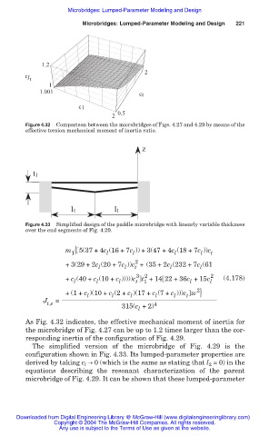
Figure 4.32 Comparison between the microbridges of Figs. 4.27 and 4.29 by means of the
effective torsion mechanical moment of inertia ratio.
z
t1
1 1 1 1
Figure 4.33 Simplified design of the paddle microbridge with linearly variable thickness
over the end segments of Fig. 4.29.
m { 5(37 + 4c (16 + 7c )) +3(47 + 4c (18 + 7c ))c
1 l l l l t
2
+3(29 + 2c (20 + 7c ))c + (35 + 2c (232 + 7c (61
l
l
l
l
t
3 2 2
+ c (40 + c (10 + c )))))c t +14 22 + 36c +15c l (4.178)
t
l
l
l
1
l
2
+ (1+ c )(10 + c (2+ c )(17 + c (7+ c )))c w }
l
l
t
l
l
l
J =
t,e 315(c +2) 4
l
As Fig. 4.32 indicates, the effective mechanical moment of inertia for
the microbridge of Fig. 4.27 can be up to 1.2 times larger than the cor-
responding inertia of the configuration of Fig. 4.29.
The simplified version of the microbridge of Fig. 4.29 is the
configuration shown in Fig. 4.33. Its lumped-parameter properties are
derived by taking c l ඎ 0 (which is the same as stating that l 2 = 0) in the
equations describing the resonant characterization of the parent
microbridge of Fig. 4.29. It can be shown that these lumped-parameter
Downloaded from Digital Engineering Library @ McGraw-Hill (www.digitalengineeringlibrary.com)
Copyright © 2004 The McGraw-Hill Companies. All rights reserved.
Any use is subject to the Terms of Use as given at the website.