
Page 219 - Mechanical design of microresonators _ modeling and applications
P. 219
0-07-145538-8_CH04_218_08/30/05
Microbridges: Lumped-Parameter Modeling and Design
218 Chapter Four
z
t1 t2
l1 l2 l1
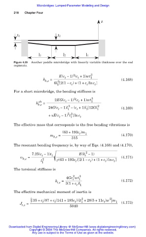
Figure 4.29 Another paddle microbridge with linearly variable thickness over the end
segments.
3
E(c Ì 1) (c +1)wt 1 3
t
t
k b,e = (4.168)
3
6l 2(1 Ì c ) + (1+ c )ln c
1 t t t
For a short microbridge, the bending stiffness is
3
2EG(c Ì 1) (c +1)wt 3
sh t t 1
k b,e =
3
24G(c Ì 1)l Ì (c +1)l 12Gl 1 2 (4.169)
t
t
1
1
2 2
+ țE(c Ì 1) t 1 ln c t
t
The effective mass that corresponds to the free bending vibrations is
(63 + 193c )m 1
t
m = (4.170)
b,e 315
The resonant bending frequency is, by way of Eqs. (4.168) and (4.170),
2
7.25(c Ì 1)t 1 E(k Ì 1)
t
t
Ȧ = (4.171)
b,e 2 ȡ(63 + 193c ) 2(1 Ì c ) + (1+ c ) ln c
l 1 t t t t
The torsional stiffness is
2
4Gc wt 1 3
t
k t,e = (4.172)
3(1+ c )l
t 1
The effective mechanical moment of inertia is
2 2
{ 35 + c (87 + c (141 + 185c )) t +28(5+11c )w }m 1
t
t
t
t
1
J t,e = 5040 (4.173)
Downloaded from Digital Engineering Library @ McGraw-Hill (www.digitalengineeringlibrary.com)
Copyright © 2004 The McGraw-Hill Companies. All rights reserved.
Any use is subject to the Terms of Use as given at the website.