
Page 216 - Mechanical design of microresonators _ modeling and applications
P. 216
0-07-145538-8_CH04_215_08/30/05
Microbridges: Lumped-Parameter Modeling and Design
Microbridges: Lumped-Parameter Modeling and Design 215
y
l1 l1
α α
w1 w1
w2 fixed
x
fixed
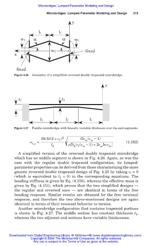
Figure 4.26 Geometry of a simplified reversed doubly trapezoid microbridge.
z
t1 t2
l1 l2 l1
Figure 4.27 Paddle microbridge with linearly variable thickness over the end segments.
20.5t(2+ c ) 2 Gc (c í 1)
w
w
l
Ȧ = (4.162)
t,e l 1 ȡD c (c í 1) +2c ln c w
l
w
2
w
A simplified version of the reversed doubly trapezoid microbridge
which has no middle segment is shown in Fig. 4.26. Again, as was the
case with the regular double trapezoid configuration, its lumped-
parameter properties can be derived from those characterizing the more
generic reversed double trapezoid design of Fig. 4.25 by taking c l = 0
(which is equivalent to l = 0) in the corresponding equations. The
2
bending stiffness is given by Eq. (4.150), whereas the effective mass is
given by Eq. (4.151), which proves that the two simplified designs –
the regular and reversed ones – are identical in terms of the free
bending response. Similar results are obtained for the free torsional
response, and therefore the two above-mentioned designs are again
identical in terms of their resonant behavior in torsion.
Another microbridge configuration that contains trapezoid portions
is shown in Fig. 4.27. The middle section has constant thickness t 2 ,
whereas the two adjacent end sections have variable thicknesses.
Downloaded from Digital Engineering Library @ McGraw-Hill (www.digitalengineeringlibrary.com)
Copyright © 2004 The McGraw-Hill Companies. All rights reserved.
Any use is subject to the Terms of Use as given at the website.