
Page 264 - Mechanical design of microresonators _ modeling and applications
P. 264
0-07-145538-8_CH05_263_08/30/05
Resonant Micromechanical Systems
Resonant Micromechanical Systems 263
y
z
x
(a) (b) (c)
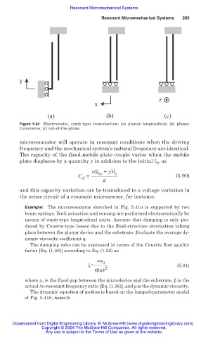
Figure 5.40 Electrostatic, comb-type transduction: (a) planar longitudinal; (b) planar
transverse; (c) out-of-the-plane.
microresonator will operate in resonant conditions when the driving
frequency and the mechanical system’s natural frequency are identical.
The capacity of the fixed-mobile plate couple varies when the mobile
plate displaces by a quantity y in addition to the initial l as
0y
İ(l 0y + y)l z
C = (5.90)
cf g
and this capacity variation can be transduced to a voltage variation in
the sense circuit of a resonant microsensor, for instance.
Example: The microresonator sketched in Fig. 5.41a is supported by two
beam springs. Both actuation and sensing are performed electrostatically by
means of comb-type longitudinal units. Assume that damping is only pro-
duced by Couette-type losses due to the fluid-structure interaction taking
place between the planar device and the substrate. Evaluate the average dy-
namic viscosity coefficient Ș.
The damping ratio can be expressed in terms of the Couette flow quality
factor [Eq. (1.46)] according to Eq. (1.26) as
Ȧz
ȟ = 0 (5.91)
ʌȕȝx ˙ 2
where z 0 is the fixed gap between the microdevice and the substrate, ȕ is the
actual-to-resonant frequency ratio [Eq. (1.16)], and ȝ is the dynamic viscosity.
The dynamic equation of motion is based on the lumped-parameter model
of Fig. 5.41b, namely
Downloaded from Digital Engineering Library @ McGraw-Hill (www.digitalengineeringlibrary.com)
Copyright © 2004 The McGraw-Hill Companies. All rights reserved.
Any use is subject to the Terms of Use as given at the website.