
Page 262 - Mechanical design of microresonators _ modeling and applications
P. 262
0-07-145538-8_CH05_261_08/30/05
Resonant Micromechanical Systems
Resonant Micromechanical Systems 261
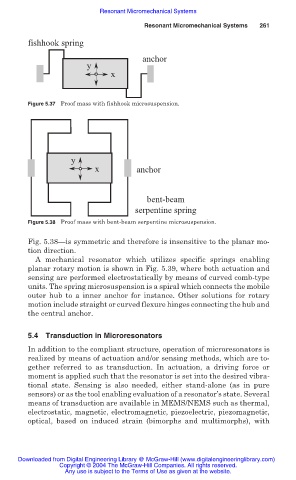
fishhook spring
anchor
y
x
Figure 5.37 Proof mass with fishhook microsuspension.
y
x anchor
bent-beam
serpentine spring
Figure 5.38 Proof mass with bent-beam serpentine microsuspension.
Fig. 5.38—is symmetric and therefore is insensitive to the planar mo-
tion direction.
A mechanical resonator which utilizes specific springs enabling
planar rotary motion is shown in Fig. 5.39, where both actuation and
sensing are performed electrostatically by means of curved comb-type
units. The spring microsuspension is a spiral which connects the mobile
outer hub to a inner anchor for instance. Other solutions for rotary
motion include straight or curved flexure hinges connecting the hub and
the central anchor.
5.4 Transduction in Microresonators
In addition to the compliant structure, operation of microresonators is
realized by means of actuation and/or sensing methods, which are to-
gether referred to as transduction. In actuation, a driving force or
moment is applied such that the resonator is set into the desired vibra-
tional state. Sensing is also needed, either stand-alone (as in pure
sensors) or as the tool enabling evaluation of a resonator’s state. Several
means of transduction are available in MEMS/NEMS such as thermal,
electrostatic, magnetic, electromagnetic, piezoelectric, piezomagnetic,
optical, based on induced strain (bimorphs and multimorphs), with
Downloaded from Digital Engineering Library @ McGraw-Hill (www.digitalengineeringlibrary.com)
Copyright © 2004 The McGraw-Hill Companies. All rights reserved.
Any use is subject to the Terms of Use as given at the website.