
Page 258 - Mechanical design of microresonators _ modeling and applications
P. 258
0-07-145538-8_CH05_257_08/30/05
Resonant Micromechanical Systems
Resonant Micromechanical Systems 257
y
z gimbal
x
2 1
m
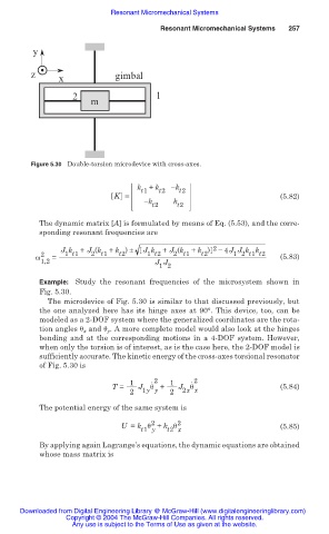
Figure 5.30 Double-torsion microdevice with cross-axes.
k t1 + k t2 ík t2
K = (5.82)
ík k
t2 t2
The dynamic matrix [A] is formulated by means of Eq. (5.53), and the corre-
sponding resonant frequencies are
J k + J (k + k ) ± J k + J (k + k ) 2 í 4J J k k
t2
1 t1
1 2 t1 t2
2 t1
2 t1
1 t2
t2
Ȧ 2 = (5.83)
1,2 J J
1 2
Example: Study the resonant frequencies of the microsystem shown in
Fig. 5.30.
The microdevice of Fig. 5.30 is similar to that discussed previously, but
the one analyzed here has its hinge axes at 90°. This device, too, can be
modeled as a 2-DOF system where the generalized coordinates are the rota-
tion angles ș x and ș y . A more complete model would also look at the hinges
bending and at the corresponding motions in a 4-DOF system. However,
when only the torsion is of interest, as is the case here, the 2-DOF model is
sufficiently accurate. The kinetic energy of the cross-axes torsional resonator
of Fig. 5.30 is
1 . 2 1 . 2
T = J ș + J ș (5.84)
2 1y y 2 2x x
The potential energy of the same system is
2
U = k ș + k ș 2 (5.85)
t1 y t2 x
By applying again Lagrange’s equations, the dynamic equations are obtained
whose mass matrix is
Downloaded from Digital Engineering Library @ McGraw-Hill (www.digitalengineeringlibrary.com)
Copyright © 2004 The McGraw-Hill Companies. All rights reserved.
Any use is subject to the Terms of Use as given at the website.