
Page 257 - Mechanical design of microresonators _ modeling and applications
P. 257
0-07-145538-8_CH05_256_08/30/05
Resonant Micromechanical Systems
256 Chapter Five
1.7
1.6
1.5
r ω 1.4
2-4
1.3
1.2
1.1
1
0 2 4 6 8 10
c l
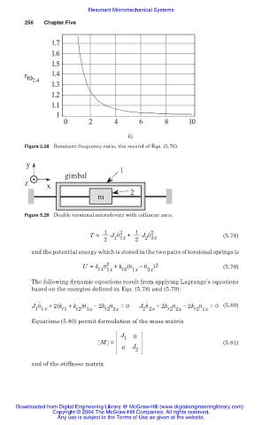
Figure 5.28 Resonant frequency ratio, the second of Eqs. (5.76).
y
1
gimbal
z x
2
m
Figure 5.29 Double torsional microdevice with collinear axes.
1 ˙ 2 1 ˙ 2
T = J ș + J ș (5.78)
2 1 1x 2 2 2x
and the potential energy which is stored in the two pairs of torsional springs is
U = k ș 2 + k (ș íș ) 2 (5.79)
t1 1x t2 1x 2x
The following dynamic equations result from applying Lagrange’s equations
based on the energies defined in Eqs. (5.78) and (5.79):
.. ..
J ș x +2(k t1 + k )ș í 2k ș =0 J ș x +2k ș í 2k ș =0 (5.80)
1 1
2 2
t2 2x
t2 1x
t2 2x
t2 1x
Equations (5.80) permit formulation of the mass matrix
J
1 0
M = (5.81)
0 J 2
and of the stiffness matrix
Downloaded from Digital Engineering Library @ McGraw-Hill (www.digitalengineeringlibrary.com)
Copyright © 2004 The McGraw-Hill Companies. All rights reserved.
Any use is subject to the Terms of Use as given at the website.