
Page 252 - Mechanical design of microresonators _ modeling and applications
P. 252
0-07-145538-8_CH05_251_08/30/05
Resonant Micromechanical Systems
Resonant Micromechanical Systems 251
6
5.5
5
r ω*
4.5
4
3.5
0 1 2 3 4 5
c
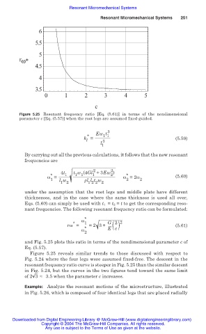
Figure 5.25 Resonant frequency ratio [Eq. (5.61)] in terms of the nondimensional
parameter c [Eq. (5.57)] when the root legs are assumed fixed-guided.
3
Ew t
* 1 1
k = (5.59)
l 3
l
1
By carrying out all the previous calculations, it follows that the new resonant
frequencies are
2
2
4t 1 t w (4Gl +3Ew )
2
1
1 1
*
*
Ȧ = Ȧ =2Ȧ (5.60)
1 l w ȡl l t w 2 2
1 2 1 2 2 2
under the assumption that the root legs and middle plate have different
thicknesses, and in the case where the same thickness is used all over,
Eqs. (5.60) can simply be used with t 1 = t 2 = t to get the corresponding reso-
nant frequencies. The following resonant frequency ratio can be formulated:
*
Ȧ
* 1 G 2 2
rȦ = =2 3+ ( ) (5.61)
Ȧ * E c
2
and Fig. 5.25 plots this ratio in terms of the nondimensional parameter c of
Eq. (5.57).
Figure 5.25 reveals similar trends to those discussed with respect to
Fig. 5.24 where the four legs were assumed fixed-free. The descent in the
resonant frequency ratio curve is steeper in Fig. 5.25 than the similar descent
in Fig. 5.24, but the curves in the two figures tend toward the same limit
of 2 3 § 3.5 when the parameter c increases.
Example: Analyze the resonant motions of the microstructure, illustrated
in Fig. 5.26, which is composed of four identical legs that are placed radially
Downloaded from Digital Engineering Library @ McGraw-Hill (www.digitalengineeringlibrary.com)
Copyright © 2004 The McGraw-Hill Companies. All rights reserved.
Any use is subject to the Terms of Use as given at the website.