
Page 255 - Mechanical design of microresonators _ modeling and applications
P. 255
0-07-145538-8_CH05_254_08/30/05
Resonant Micromechanical Systems
254 Chapter Five
..
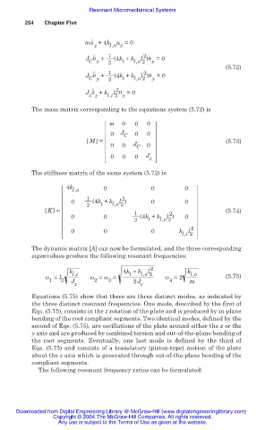
mu +4k u =0
z l,o z
.. 1
2
J ș + (4k + k l )ș =0
C x 2 t l,o 2 x
(5.72)
.. 1 2
J ș + (4k + k l )ș =0
C y 2 t l,o 2 y
.. 2
J ș + k l ș =0
z z l,i 2 z
The mass matrix corresponding to the equations system (5.72) is
m 0 0 0
0 J C 0 0
M = (5.73)
0 0 J C 0
0 0 0 J z
The stiffness matrix of the same system (5.72) is
4k
l,o 0 0 0
1 2
0 (4k + k l ) 0 0
2 t l,o 2
K = 1 2 (5.74)
0 0 (4k + k l ) 0
2 t l,o 2
2
0 0 0 k l
l,i 2
The dynamic matrix [A] can now be formulated, and the three corresponding
eigenvalues produce the following resonant frequencies:
2
k l,i 4k + k l,o 2 k l,o
l
t
Ȧ = l Ȧ = Ȧ = Ȧ =2 (5.75)
1 2 J 2 3 2J 4 m
z c
Equations (5.75) show that there are three distinct modes, as indicated by
the three distinct resonant frequencies. One mode, described by the first of
Eqs. (5.75), consists in the z rotation of the plate and is produced by in-plane
bending of the root compliant segments. Two identical modes, defined by the
second of Eqs. (5.75), are oscillations of the plate around either the x or the
y axis and are produced by combined torsion and out-of-the-plane bending of
the root segments. Eventually, one last mode is defined by the third of
Eqs. (5.75) and consists of a translatory (piston-type) motion of the plate
about the z axis which is generated through out-of-the-plane bending of the
compliant segments.
The following resonant frequency ratios can be formulated:
Downloaded from Digital Engineering Library @ McGraw-Hill (www.digitalengineeringlibrary.com)
Copyright © 2004 The McGraw-Hill Companies. All rights reserved.
Any use is subject to the Terms of Use as given at the website.