
Page 251 - Mechanical design of microresonators _ modeling and applications
P. 251
0-07-145538-8_CH05_250_08/30/05
Resonant Micromechanical Systems
250 Chapter Five
10
9
8
r ω 7
6
5
4
0 1 2 3 4 5
c
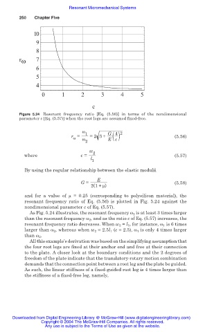
Figure 5.24 Resonant frequency ratio [Eq. (5.56)] in terms of the nondimensional
parameter c [Eq. (5.57)] when the root legs are assumed fixed-free.
Ȧ 1 G 4 2
r = =2 3+ ( ) (5.56)
Ȧ
Ȧ
2 E c
w 2
where c = (5.57)
l
1
By using the regular relationship between the elastic modulii
E
G = (5.58)
2(1+ ȝ)
and for a value of ȝ = 0.25 (corresponding to polysilicon material), the
resonant frequency ratio of Eq. (5.56) is plotted in Fig. 5.24 against the
nondimensional parameter c of Eq. (5.57).
As Fig. 5.24 illustrates, the resonant frequency Ȧ 1 is at least 3 times larger
than the resonant frequency Ȧ 2 , and as the ratio c of Eq. (5.57) increases, the
resonant frequency ratio decreases. When w 2 = l 1 , for instance, Ȧ 1 is 6 times
larger than Ȧ 2 , whereas when w 2 = 2.5l 1 (c = 2.5), Ȧ 1 is only 4 times larger
than Ȧ 2 .
All this example’s derivation was based on the simplifying assumption that
the four root legs are fixed at their anchor end and free at their connection
to the plate. A closer look at the boundary conditions and the 2 degrees of
freedom of the plate indicate that the translatory-rotary motion combination
demands that the connection point between a root leg and the plate be guided.
As such, the linear stiffness of a fixed-guided root leg is 4 times larger than
the stiffness of a fixed-free leg, namely,
Downloaded from Digital Engineering Library @ McGraw-Hill (www.digitalengineeringlibrary.com)
Copyright © 2004 The McGraw-Hill Companies. All rights reserved.
Any use is subject to the Terms of Use as given at the website.