
Page 253 - Mechanical design of microresonators _ modeling and applications
P. 253
0-07-145538-8_CH05_252_08/30/05
Resonant Micromechanical Systems
252 Chapter Five
y
m
z x
l 2
l 1
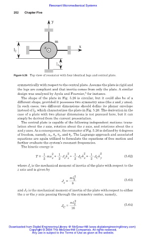
Figure 5.26 Top view of resonator with four identical legs and central plate.
symmetrically with respect to the central plate. Assume the plate is rigid and
the legs are compliant and that inertia comes from only the plate. A similar
5
design was analyzed by Ayela and Fournier, for instance.
The shape of the plate in Fig. 5.26 is circular, but it could also be of a
different shape, provided it possesses two symmetry axes (the x and y axes).
In such cases, two different dimensions should define its planar envelope
instead of l 2 , which characterizes the plate in Fig. 5.26. The derivation in the
case of a plate with two planar dimensions is not pursued here, but it can
simply be derived from the current presentation.
The central plate is capable of the following independent motions: trans-
lation about the z axis, rotation about the z axis, and rotations about the x
and y axes. As a consequence, the resonator of Fig. 5.26 is defined by 4 degrees
of freedom, namely, u z , ș z , ș x , and ș y . The Lagrange approach and associated
equations are again utilized to formulate the equations of free motion and
further evaluate the system’s resonant frequencies.
The kinetic energy is
1 . 2 1 .2 1 . 2 1 . 2
T = mu + J ș + J ș + J ș (5.62)
C y
z z
C x
z
2 2 2 2
where J z is the mechanical moment of inertia of the plate with respect to the
z axis and is given by
ml 2 2
J = 8 (5.63)
z
and J C is the mechanical moment of inertia of the plate with respect to either
the x or the y axis passing through the symmetry center, namely,
2
ml
J = 2 (5.64)
C 16
Downloaded from Digital Engineering Library @ McGraw-Hill (www.digitalengineeringlibrary.com)
Copyright © 2004 The McGraw-Hill Companies. All rights reserved.
Any use is subject to the Terms of Use as given at the website.