
Page 248 - Mechanical design of microresonators _ modeling and applications
P. 248
0-07-145538-8_CH05_247_08/30/05
Resonant Micromechanical Systems
Resonant Micromechanical Systems 247
2
ω * , te /ω , te 10
1.9994
0.001
c w
c t ´ 0.1 2
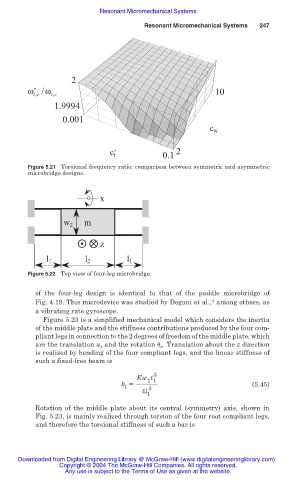
Figure 5.21 Torsional frequency ratio: comparison between symmetric and asymmetric
microbridge designs.
x
m
w 2
z
l 1 l 2 l 1
Figure 5.22 Top view of four-leg microbridge.
of the four-leg design is identical to that of the paddle microbridge of
4
Fig. 4.19. This microdevice was studied by Degani et al., among others, as
a vibrating rate gyroscope.
Figure 5.23 is a simplified mechanical model which considers the inertia
of the middle plate and the stiffness contributions produced by the four com-
pliant legs in connection to the 2 degrees of freedom of the middle plate, which
are the translation u z and the rotation ș x . Translation about the z direction
is realized by bending of the four compliant legs, and the linear stiffness of
such a fixed-free beam is
3
Ew t
1 1
k = (5.45)
l 3
4l
1
Rotation of the middle plate about its central (symmetry) axis, shown in
Fig. 5.23, is mainly realized through torsion of the four root compliant legs,
and therefore the torsional stiffness of such a bar is
Downloaded from Digital Engineering Library @ McGraw-Hill (www.digitalengineeringlibrary.com)
Copyright © 2004 The McGraw-Hill Companies. All rights reserved.
Any use is subject to the Terms of Use as given at the website.