
Page 249 - Mechanical design of microresonators _ modeling and applications
P. 249
0-07-145538-8_CH05_248_08/30/05
Resonant Micromechanical Systems
248 Chapter Five
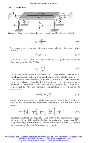
k t k t
x
k l
k l
k l k l
u z
Figure 5.23 Four-leg microbridge: lumped-parameter model and degrees of freedom.
3
Gw t
1 1
k = (5.46)
t 3l
1
The mass of the whole microstructure comes only from the middle plate,
which is
m = ȡl w t (5.47)
2 2 2
and the mechanical moment of inertia of the same plate with respect to
the x axis shown in Fig. 5.23 is
2
mw 2
J = (5.48)
C 12
The assumption is made in this model that the thickness of the identical
compliant legs t 1 is different from the thickness of the middle plate t 2 .
To derive the free response in matrix form for this 2-DOF model, La-
grange’s equations are employed. The kinetic energy of the microsystem is
produced by z translation and x rotation of the middle plate, which is as-
sumed rigid and the only component contributing to overall inertia. Its
expression is
1 2 1 ˙ 2
T = mu ˙ + J ș (5.49)
2 z 2 C x
Similarly, the potential energy of the microsystem is produced through elas-
tic bending and torsion deformations of the four identical root components,
namely,
l( z )
1 w 2 2 1 w 2 2 1 2
U =2 k u + 2ș ) + k u í +4 k ș (5.50)
2 l( z 2 2ș 2 t x
x x
Equation (5.50) took into account the fact that due to superimposed transla-
tion and rotation of the middle platform, two sets of springs deform differ-
ently in bending. For two of them the total deflection is u z + ș x w 2 /2, whereas
for the other two the total deflection is u z – ș x w 2 /2.
Downloaded from Digital Engineering Library @ McGraw-Hill (www.digitalengineeringlibrary.com)
Copyright © 2004 The McGraw-Hill Companies. All rights reserved.
Any use is subject to the Terms of Use as given at the website.