
Page 246 - Mechanical design of microresonators _ modeling and applications
P. 246
0-07-145538-8_CH05_245_08/30/05
Resonant Micromechanical Systems
Resonant Micromechanical Systems 245
w 1
x
m
w 2
l 1 l 1
z
l 2
(a) (b)
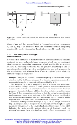
Figure 5.20 Torsion paddle microbridge: (a) geometry; (b) simplified model with degrees
of freedom.
these values and the ranges allotted to the nondimensional parameters
c l and c w , Fig. 5.19 indicates that the torsional resonant frequency
predicted by model I is smaller than that produced by model III.
5.2.3 Other examples of beam-type
microresonators
Several other examples of microresonators are discussed next that are
designed by using relatively large segments which can be considered
rigid, connected to smaller components which are flexible. As a conse-
quence, all following resonators will be qualified according to the as-
sumptions of model I, where the inertia fraction was only produced by
the massive segment whereas the stiffness was given by the relatively
smaller compliant segments.
Example: Analyze the torsional resonant frequency of the torsional bridge
sketched in Fig. 5.20a and compare it to the corresponding resonant fre-
quency of the regular bridge design illustrated in Fig. 4.19.
1
The design of Fig. 5.20a is analyzed by Xiao et al. as an electrostatic tor-
2
sional actuator and by Selvakumar and Najafi as a microaccelerometer, but
it can also be utilized as a torsional resonator for mass addition detection
purposes—the subject of mass addition detection is studied more thoroughly
in Chap. 6. The assumption made here is that the central segment is rigid
(and possesses a mass m, as indicated in Fig. 5.20b), whereas the identical
root segments are compliant and are considerably lighter than the middle
segment such that their inertia contribution can be neglected.
Compared to the paddle microbridge of Fig. 4.19, the design sketched in
Fig. 5.20a is quite similar except for the middle segment which is placed asym-
metrically with respect to the longitudinal axis of the hinges. Figure 5.20b
indicates the main possible motions (degrees of freedom) which are
the rotation around the x axis (implying torsion of the root segments) and
Downloaded from Digital Engineering Library @ McGraw-Hill (www.digitalengineeringlibrary.com)
Copyright © 2004 The McGraw-Hill Companies. All rights reserved.
Any use is subject to the Terms of Use as given at the website.