Page 256 - Mechanical design of microresonators _ modeling and applications
P. 256

0-07-145538-8_CH05_255_08/30/05


                                                 Resonant Micromechanical Systems

                                                             Resonant Micromechanical Systems  255


                                   100                                       0.1
                              r ω
                                1-2
                                      0
                                      1
                                                                          c t ´


                                                c l               0.001
                                                               10
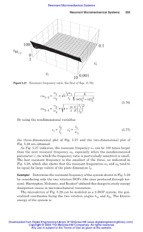
                              Figure 5.27 Resonant frequency ratio, the first of Eqs. (5.76).


                                                    Ȧ 1    l w       E
                                                           2 1
                                             rȦ   =    = 3
                                               1í2  Ȧ       t       2     2
                                                     2       1  16Gl +3El
                                                                    1    2
                                                                                          (5.76)
                                                    Ȧ             l  2
                                                             3 E( l )
                                             rȦ   =  2  = 1+  16 G  1
                                               2í4  Ȧ
                                                     4            2
                                By using the nondimensional variables
                                                       l 2      t 1
                                                             ƍ
                                                   c =      c =                           (5.77)
                                                    l  l     t  w
                                                        1        1
                                the three-dimensional plot of Fig. 5.27 and the  two-dimensional plot  of
                                Fig. 5.28 are obtained.
                                  As Fig. 5.27 indicates, the resonant frequency Ȧ 1  can be 100 times larger
                                than the next resonant frequency Ȧ 2 , especially when the nondimensional
                                parameter cƍ t  (to which the frequency ratio is particularly sensitive) is small.
                                The last resonant frequency  is the  smallest of the three,  as indicated  in
                                Fig. 5.28, which also shows that the resonant frequencies Ȧ 2  and Ȧ 4  tend to
                                be equal for large values of the plate dimension l 2 .

                                Example: Determine the resonant frequency of the system shown in Fig. 5.29
                                by considering only the two rotation DOFs (the ones produced through tor-
                                                                 6
                                sion). Harrington, Mohanty, and Roukes  utilized this design to study energy
                                dissipation issues in micromechanical resonators.
                                  The microdevice of Fig. 5.29 can be modeled as a 2-DOF system, the gen-
                                eralized coordinates being the two rotation angles ș 1x  and ș 2x . The kinetic
                                energy of the system is


                           Downloaded from Digital Engineering Library @ McGraw-Hill (www.digitalengineeringlibrary.com)
                                      Copyright © 2004 The McGraw-Hill Companies. All rights reserved.
                                        Any use is subject to the Terms of Use as given at the website.
   251   252   253   254   255   256   257   258   259   260   261