
Page 260 - Mechanical design of microresonators _ modeling and applications
P. 260
0-07-145538-8_CH05_259_08/30/05
Resonant Micromechanical Systems
Resonant Micromechanical Systems 259
y
k k
m
x
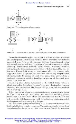
Figure 5.32 Two-spring planar microresonator.
m z x
m
k k
k k
(a) (b)
Figure 5.33 Two-spring out-of-the-plane microresonators: (a) bending; (b) torsional.
Several spring designs that are currently utilized in microresonators
and enable parallel motion of a resonant device above the substrate are
presented next. Figures. 5.34 through 5.38 are illustrations of spring
pairs which realize both the suspension of the microresonator and the
elasticity (compliance) function. More details regarding stiffness
7
calculations for those springs are provided by Lobontiu and Garcia, for
instance. Figure 5.34 shows a proof mass which is symmetrically
supported by two U springs. The actuation and sensing are performed
electrostatically by means of comb-type units. This microsystem is
designed to produce unidirectional frontal motion of the proof mass
about the x direction.
Another planar elastic suspension is the folded beam, which is
illustrated in Fig. 5.35 where the proof mass also vibrates about a single
direction (the y direction). The designs of Figs. 5.34 and 5.35 are both
of a frontal-type class.
Other two-spring planar microsuspensions are schematically shown
in Figs. 5.36 through 5.38; they are solutions enabling planar
translation of a proof mass about two perpendicular directions x and
y. Eventually, full planar motion (with the z-direction rotation included)
is also permitted by these spring designs.
The serpentine spring (shown in Fig. 5.36) is composed of several iden-
tical units that are serially connected. The units can also be scaled down
7
or up in another design variant (see Lobontiu and Garcia for instance),
Downloaded from Digital Engineering Library @ McGraw-Hill (www.digitalengineeringlibrary.com)
Copyright © 2004 The McGraw-Hill Companies. All rights reserved.
Any use is subject to the Terms of Use as given at the website.