Page 269 - Mechanical design of microresonators _ modeling and applications
P. 269

0-07-145538-8_CH05_268_08/30/05


                                                 Resonant Micromechanical Systems

                              268   Chapter Five

                                          bending axis
                                                                                       F
                                                      I                torsion axis     I
                                              F            F                                  B
                                                    R
                                                                                      F
                                                     B
                                             (a)                               (b)
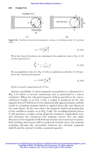
                              Figure 5.44 Cantilever-based electromagnetic sensing: (a) bending mode; (b) torsional
                              mode.

                                                            d  E
                                                    Ȧ =5.6                               (5.103)
                                                      r     2  ȡ
                                                           l
                                When the forced vibrations are undamped, the amplitude ratio of Eq. (1.15)
                                can be expressed as
                                                    X        1
                                                       =
                                                    X            2                       (5.104)
                                                     st  1 í (Ȧ Ȧ )
                                                              / r
                                For an amplitude ratio of 2, Eq. (5.104) in combination with Eq. (5.103) pro-
                                duces the excitation frequency

                                                             d  E
                                                    Ȧ =3.955                             (5.105)
                                                            l 2  ȡ
                                which is equal to approximately 0.71Ȧ r .
                                Another possibility of electromagnetic transduction is illustrated in
                              Fig. 5.44 where  a circular conducting wire is patterned to a micro-
                              cantilever. When the external magnetic field is parallel to the micro-
                              cantilever length, as  in Fig.  5.44a, a  couple is produced by the  two
                              opposite forces F which act at two diametrically opposed points, and the
                              result is a bending moment which is applied about the axis shown in
                              the same figure. In the case where the magnetic field is perpendicular
                              to the cantilever length, as in Fig. 5.44b, the resulting Lorentz forces
                              F will generate a couple acting along the member’s longitudinal axis,
                              and therefore the  cantilever will undergo torsion. For any other
                              direction of the magnetic field B situated in the microcantilever’s plane,
                              both bending and torsion will be produced. In both cases, the moment
                              resulting through  the  interaction  between the external magnetic
                              field B and the current I yields a moment equal to


                           Downloaded from Digital Engineering Library @ McGraw-Hill (www.digitalengineeringlibrary.com)
                                      Copyright © 2004 The McGraw-Hill Companies. All rights reserved.
                                        Any use is subject to the Terms of Use as given at the website.
   264   265   266   267   268   269   270   271   272   273   274