
Page 274 - Mechanical design of microresonators _ modeling and applications
P. 274
0-07-145538-8_CH05_273_08/30/05
Resonant Micromechanical Systems
Resonant Micromechanical Systems 273
y (sense direction)
cs
ks
cd
m
Fd x (drive direction)
kd
ω
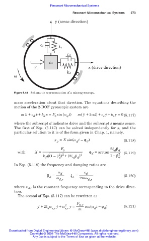
Figure 5.48 Schematic representation of a microgyroscope.
mass acceleration about that direction. The equations describing the
motion of the 2-DOF gyroscopic system are
mx ˙˙ + c x ˙ + k x = F sin (Ȧ t) m( y ˙˙ +2Ȧx ˙) + c y ˙ + k y =0 (5.117)
d
0
d
s
s
d
where the subscript d indicates drive and the subscript s means sense.
The first of Eqs. (5.117) can be solved independently for x, and the
particular solution to it is of the form given in Chap. 1, namely,
x = X sin(Ȧ t – ́ ) (5.118)
p d d
F 0 2ȟ ȕ
d d
with X = ́ = arctan 2 (5.119)
d
2 2
k d (1– ȕ ) + (2ȟ ȕ ) 2 1– ȕ d
d
d d
In Eqs. (5.119) the frequency and damping ratios are
Ȧ c
ȕ = d ȟ = d (5.120)
d Ȧ d 2mȦ
d,r d,r
where Ȧ d,r is the resonant frequency corresponding to the drive direc-
tion.
The second of Eqs. (5.117) can be rewritten as
F 0,y
y ˙˙ +2ȟ Ȧ y ˙ + Ȧ 2 y = cos(Ȧ t í ́ ) (5.121)
s s,r s,r m d d
Downloaded from Digital Engineering Library @ McGraw-Hill (www.digitalengineeringlibrary.com)
Copyright © 2004 The McGraw-Hill Companies. All rights reserved.
Any use is subject to the Terms of Use as given at the website.