
Page 273 - Mechanical design of microresonators _ modeling and applications
P. 273
0-07-145538-8_CH05_272_08/30/05
Resonant Micromechanical Systems
272 Chapter Five
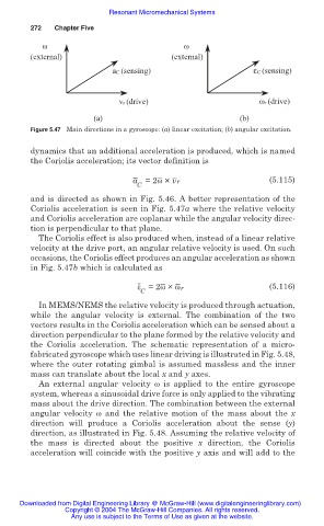
ω ω
(external) (external)
aC (sensing) εC (sensing)
vr (drive) ωr (drive)
(a) (b)
Figure 5.47 Main directions in a gyroscope: (a) linear excitation; (b) angular excitation.
dynamics that an additional acceleration is produced, which is named
the Coriolis acceleration; its vector definition is
a =2Ȧ × vr (5.115)
C
and is directed as shown in Fig. 5.46. A better representation of the
Coriolis acceleration is seen in Fig. 5.47a where the relative velocity
and Coriolis acceleration are coplanar while the angular velocity direc-
tion is perpendicular to that plane.
The Coriolis effect is also produced when, instead of a linear relative
velocity at the drive port, an angular relative velocity is used. On such
occasions, the Coriolis effect produces an angular acceleration as shown
in Fig. 5.47b which is calculated as
İ =2Ȧ × Ȧr (5.116)
C
In MEMS/NEMS the relative velocity is produced through actuation,
while the angular velocity is external. The combination of the two
vectors results in the Coriolis acceleration which can be sensed about a
direction perpendicular to the plane formed by the relative velocity and
the Coriolis acceleration. The schematic representation of a micro-
fabricated gyroscope which uses linear driving is illustrated in Fig. 5.48,
where the outer rotating gimbal is assumed massless and the inner
mass can translate about the local x and y axes.
An external angular velocity Ȧ is applied to the entire gyroscope
system, whereas a sinusoidal drive force is only applied to the vibrating
mass about the drive direction. The combination between the external
angular velocity Ȧ and the relative motion of the mass about the x
direction will produce a Coriolis acceleration about the sense (y)
direction, as illustrated in Fig. 5.48. Assuming the relative velocity of
the mass is directed about the positive x direction, the Coriolis
acceleration will coincide with the positive y axis and will add to the
Downloaded from Digital Engineering Library @ McGraw-Hill (www.digitalengineeringlibrary.com)
Copyright © 2004 The McGraw-Hill Companies. All rights reserved.
Any use is subject to the Terms of Use as given at the website.