
Page 277 - Mechanical design of microresonators _ modeling and applications
P. 277
0-07-145538-8_CH05_276_08/30/05
Resonant Micromechanical Systems
276 Chapter Five
ēC y (sense)
outer gimbal
inner gimbal
wr
m
x
torsion hinges
w
z (input)
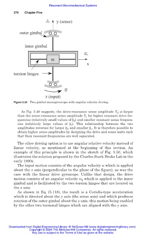
Figure 5.50 Two-gimbal microgyroscope with angular velocity driving.
As Fig. 5.49 suggests, the drive-resonance sense amplitude Y d is larger
than the sense-resonance sense amplitude Y s for higher resonant drive fre-
quencies (relatively small values of ȕ d ) and smaller resonant sense frequen-
cies (relatively large values of ȕ s ). This relationship between the two
amplitudes reverses for larger ȕ d and smaller ȕ s . It is therefore possible to
obtain higher sense amplitudes by designing the drive and sense units such
that their resonant frequencies are well separated.
The other driving option is to use angular relative velocity instead of
linear velocity, as mentioned at the beginning of this section. An
example of this principle is shown in the sketch of Fig. 5.50, which
illustrates the solution proposed by the Charles Stark Drake Lab in the
early 1990s.
The input motion consists of the angular velocity Ȧ which is applied
about the z axis (perpendicular to the plane of the figure), as was the
case with the linear drive gyroscope. Unlike that design, the drive
motion consists of an angular velocity Ȧ d which is applied to the inner
gimbal and is facilitated by the two torsion hinges that are located on
the x axis.
As shown in Eq. (5.116), the result is a Coriolis-type acceleration
which is directed about the y axis (the sense axis) and which produces
rotation of the outer gimbal about the y axis, this motion being enabled
by the other two torsional hinges which are aligned with the y axis.
Downloaded from Digital Engineering Library @ McGraw-Hill (www.digitalengineeringlibrary.com)
Copyright © 2004 The McGraw-Hill Companies. All rights reserved.
Any use is subject to the Terms of Use as given at the website.