
Page 279 - Mechanical design of microresonators _ modeling and applications
P. 279
0-07-145538-8_CH05_278_08/30/05
Resonant Micromechanical Systems
278 Chapter Five
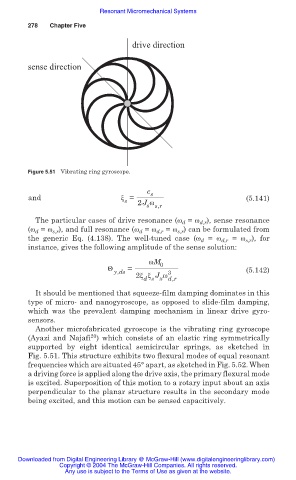
drive direction
sense direction
Figure 5.51 Vibrating ring gyroscope.
c s
and ȟ = (5.141)
s 2J Ȧ
s s,r
The particular cases of drive resonance (Ȧ d = Ȧ d,r ), sense resonance
(Ȧ = Ȧ ), and full resonance (Ȧ = Ȧ = Ȧ ) can be formulated from
d
s,r
s,r
d,r
d
the generic Eq. (4.138). The well-tuned case (Ȧ d = Ȧ d,r = Ȧ s,r ), for
instance, gives the following amplitude of the sense solution:
ȦM 0
Ĭ =
y,ds 3 (5.142)
2ȟ ȟ J Ȧ
d s x d,r
It should be mentioned that squeeze-film damping dominates in this
type of micro- and nanogyroscope, as opposed to slide-film damping,
which was the prevalent damping mechanism in linear drive gyro-
sensors.
Another microfabricated gyroscope is the vibrating ring gyroscope
20
(Ayazi and Najafi ) which consists of an elastic ring symmetrically
supported by eight identical semicircular springs, as sketched in
Fig. 5.51. This structure exhibits two flexural modes of equal resonant
frequencies which are situated 45° apart, as sketched in Fig. 5.52. When
a driving force is applied along the drive axis, the primary flexural mode
is excited. Superposition of this motion to a rotary input about an axis
perpendicular to the planar structure results in the secondary mode
being excited, and this motion can be sensed capacitively.
Downloaded from Digital Engineering Library @ McGraw-Hill (www.digitalengineeringlibrary.com)
Copyright © 2004 The McGraw-Hill Companies. All rights reserved.
Any use is subject to the Terms of Use as given at the website.