Page 283 - Mechanical design of microresonators _ modeling and applications
P. 283

0-07-145538-8_CH05_282_08/30/05


                                                 Resonant Micromechanical Systems

                              282   Chapter Five


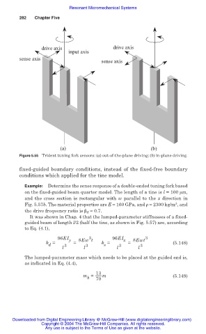
                                      drive axis                  drive axis
                                                 input axis
                              sense axis
                                                             sense axis


                                              (a)                               (b)
                              Figure 5.55 Trident tuning fork sensors: (a) out-of-the-plane driving; (b) in-plane driving.

                              fixed-guided boundary conditions, instead of the fixed-free boundary
                              conditions which applied for the tine model.
                                Example:  Determine the sense response of a double-ended tuning fork based
                                on the fixed-guided beam quarter model. The length of a tine is l = 100 ȝm,
                                and the cross section is rectangular with w parallel to  the  x direction in
                                                                                          3
                                Fig. 5.57b. The material properties are E = 160 GPa, and ȡ = 2300 kg/m , and
                                the drive frequency ratio is ȕ d  = 0.7.
                                  It was shown in Chap. 4 that the lumped-parameter stiffnesses of a fixed-
                                guided beam of length l/2 (half the tine, as shown in Fig. 5.57) are, according
                                to Eq. (4.1),
                                             96EI y  8Ew t        96EI x  8Ewt 3
                                                         3
                                        k =        =         k =        =                (5.148)
                                                              s
                                         d
                                              l  3     l 3         l 3     l  3
                                The lumped-parameter mass which needs to be placed at the guided end is,
                                as indicated in Eq. (4.4),
                                                           13
                                                      m =     m                          (5.149)
                                                        b  70


                           Downloaded from Digital Engineering Library @ McGraw-Hill (www.digitalengineeringlibrary.com)
                                      Copyright © 2004 The McGraw-Hill Companies. All rights reserved.
                                        Any use is subject to the Terms of Use as given at the website.
   278   279   280   281   282   283   284   285   286   287   288