Page 285 - Mechanical design of microresonators _ modeling and applications
P. 285

0-07-145538-8_CH05_284_08/30/05


                                                 Resonant Micromechanical Systems

                              284   Chapter Five
                                                                 z
                               symmetry axes                            ω

                                                                          F
                                                         x


                                      (a)                          (b)
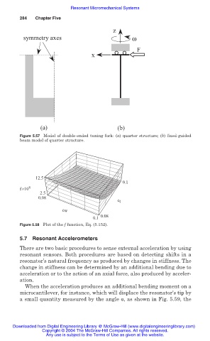
                              Figure 5.57 Model of double-ended tuning fork: (a) quarter structure; (b) fixed-guided
                              beam model of quarter structure.


                                    12.5
                                                                     0.1
                              f×10 8
                                     2.5
                                     0.08
                                                                   c t
                                              cw
                                                          0.1  0.08
                              Figure 5.58 Plot of the f function, Eq. (5.152).

                              5.7 Resonant Accelerometers

                              There are two basic procedures to sense external acceleration by using
                              resonant sensors. Both procedures are based on detecting shifts in a
                              resonator’s natural frequency as produced by changes in stiffness. The
                              change in stiffness can be determined by an additional bending due to
                              acceleration or to the action of an axial force, also produced by acceler-
                              ation.
                                When the acceleration produces an additional bending moment on a
                              microcantilever, for instance, which will displace the resonator’s tip by
                              a small quantity measured by the angle Į, as shown in Fig. 5.59, the


                           Downloaded from Digital Engineering Library @ McGraw-Hill (www.digitalengineeringlibrary.com)
                                      Copyright © 2004 The McGraw-Hill Companies. All rights reserved.
                                        Any use is subject to the Terms of Use as given at the website.
   280   281   282   283   284   285   286   287   288   289   290