
Page 286 - Mechanical design of microresonators _ modeling and applications
P. 286
0-07-145538-8_CH05_285_08/30/05
Resonant Micromechanical Systems
Resonant Micromechanical Systems 285
α
Figure 5.59 Displaced fixed-free microcantilever.
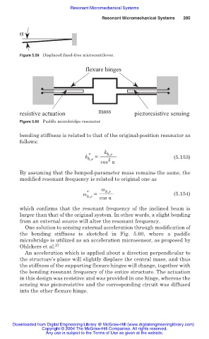
flexure hinges
resistive actuation mass piezoresistive sensing
Figure 5.60 Paddle microbridge resonator.
bending stiffness is related to that of the original-position resonator as
follows:
k b,e
*
k b,e = (5.153)
2
cos Į
By assuming that the lumped-parameter mass remains the same, the
modified resonant frequency is related to original one as
Ȧ b,e
Ȧ * = (5.154)
b,e cos Į
which confirms that the resonant frequency of the inclined beam is
larger than that of the original system. In other words, a slight bending
from an external source will alter the resonant frequency.
One solution to sensing external acceleration through modification of
the bending stiffness is sketched in Fig. 5.60, where a paddle
microbridge is utilized as an acceleration microsensor, as proposed by
Ohlckers et al. 27
An acceleration which is applied about a direction perpendicular to
the structure’s plane will slightly displace the central mass, and thus
the stiffness of the supporting flexure hinges will change, together with
the bending resonant frequency of the entire structure. The actuation
in this design was resistive and was provided in one hinge, whereas the
sensing was piezoresistive and the corresponding circuit was diffused
into the other flexure hinge.
Downloaded from Digital Engineering Library @ McGraw-Hill (www.digitalengineeringlibrary.com)
Copyright © 2004 The McGraw-Hill Companies. All rights reserved.
Any use is subject to the Terms of Use as given at the website.