
Page 282 - Mechanical design of microresonators _ modeling and applications
P. 282
0-07-145538-8_CH05_281_08/30/05
Resonant Micromechanical Systems
Resonant Micromechanical Systems 281
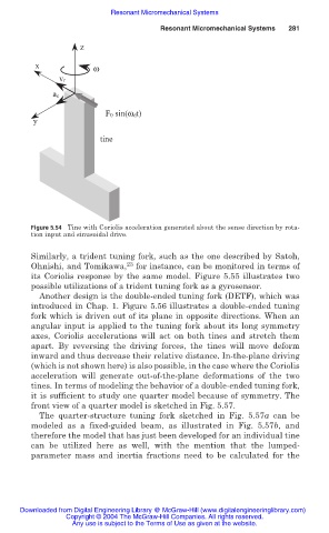
z
x ω
vr
ac
F0 sin(ωdt)
y
tine
Figure 5.54 Tine with Coriolis acceleration generated about the sense direction by rota-
tion input and sinusoidal drive.
Similarly, a trident tuning fork, such as the one described by Satoh,
23
Ohnishi, and Tomikawa, for instance, can be monitored in terms of
its Coriolis response by the same model. Figure 5.55 illustrates two
possible utilizations of a trident tuning fork as a gyrosensor.
Another design is the double-ended tuning fork (DETF), which was
introduced in Chap. 1. Figure 5.56 illustrates a double-ended tuning
fork which is driven out of its plane in opposite directions. When an
angular input is applied to the tuning fork about its long symmetry
axes, Coriolis accelerations will act on both tines and stretch them
apart. By reversing the driving forces, the tines will move deform
inward and thus decrease their relative distance. In-the-plane driving
(which is not shown here) is also possible, in the case where the Coriolis
acceleration will generate out-of-the-plane deformations of the two
tines. In terms of modeling the behavior of a double-ended tuning fork,
it is sufficient to study one quarter model because of symmetry. The
front view of a quarter model is sketched in Fig. 5.57.
The quarter-structure tuning fork sketched in Fig. 5.57a can be
modeled as a fixed-guided beam, as illustrated in Fig. 5.57b, and
therefore the model that has just been developed for an individual tine
can be utilized here as well, with the mention that the lumped-
parameter mass and inertia fractions need to be calculated for the
Downloaded from Digital Engineering Library @ McGraw-Hill (www.digitalengineeringlibrary.com)
Copyright © 2004 The McGraw-Hill Companies. All rights reserved.
Any use is subject to the Terms of Use as given at the website.