
Page 326 - Mechanical design of microresonators _ modeling and applications
P. 326
0-07-145538-8_CH06_325_08/30/05
Microcantilever and Microbridge Systems for Mass Detection
Microcantilever and Microbridge Systems for Mass Detection 325
1.15
1
ω b,0 / ω b
1
0 0
c t
c l 0.01
1 1
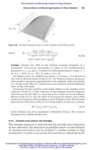
Figure 6.26 Bending frequency ratio in terms of length and thickness ratios.
3c (1 c )(1+ c c )
l
l
E t
where A =
1+ c c {4+ c 6+ c (4+ c c ) (6.72)
E t
t
E t
t
c 3+ c (6+ c (4+ c c )) }
l t t E t
Example: Analyze the shift in the bending resonant frequency of a
rectangular cross-section microbridge in terms of the nondimensional
parameters c l , c t , c E , and c ȡ . Consider the following parameter ranges: c l ĺ
[0, 1], c t ĺ [0.01, 1], c E ĺ [0.1, 1], and c ȡ ĺ [0.5, 5].
By taking c l and c t as variables, also when c E = 0.2 and c ȡ = 0.5, the plot of
Fig. 6.26 is obtained based on Eq. (6.71). The bending resonant frequency
ratio reaches a maximum approximately at the midpoint of the microbridge
(c l = 0.5) for every value of c t , and increases quasi-linearly with the thickness
ratio, as Fig. 6.26 shows.
Increasing Young’s modulus of the patch relative to the modulus of the
substrate results in a slight reduction in the bending resonant frequency
ratio because the net effect is a decrease in the overall structural stiffness.
Shown in Fig. 6.27 is also the effect of increasing the density ratio, which
results in an increase of the bending resonant frequency ratio. This becomes
more obvious if the factor in Eq. (6.71) is made explicit in terms of c ȡ , namely,
1+ f f = 1+ f c c c (6.73)
p m p l t ȡ
which indicates the above-mentioned relationship between the resonant
frequency ratio and the density ratio.
6.4.2 Variable-cross-section microbridges
The resonant approach is analyzed only for pointlike mass deposition
in this subsection. The deposition of pointlike masses on microbridges
of variable-cross-section can be studied in a similar manner to that
developed for variable-cross-section microcantilevers. Equations (6.45)
Downloaded from Digital Engineering Library @ McGraw-Hill (www.digitalengineeringlibrary.com)
Copyright © 2004 The McGraw-Hill Companies. All rights reserved.
Any use is subject to the Terms of Use as given at the website.