Page 813 - Mechanical Engineers' Handbook (Volume 2)
P. 813

804   Neural Networks in Feedback Control Systems

                          McClamroch and others). The filtered position-tracking error in q (t)is r(t), that is, r(t)
                                    27
                                                                              1
                          q 1d    q with q (t) the desired trajectory in the plane of the surface. The desired force is
                                      1d
                                1
                                                                           ˜
                          described by 
 (t) and the force exertion error is captured in 
(t)    
(t)   
 (t) with 
(t)
                                                                                       d
                                     d
                          describing the actual measured force exerted by the manipulator. The position-tracking gain
                          is K and the force-tracking gain is K . f
                             v
           6 FEEDFORWARD CONTROL STRUCTURES FOR ACTUATOR COMPENSATION
                          Industrial, aerospace, DoD, and MEMS assembly systems have actuators that generally con-
                          tain deadzone, backlash, and hysteresis. Since these actuator nonlinearities appear in the
                          feedforward loop, the NN compensator must also appear in the feedforward loop. The design
                          problem for neurocontrollers where the NN appears in the feedforward loop is significantly
                          more complex than for feedback NN controllers. Details are given in Ref. 28.

           6.1  Feedforward Neurocontroller for Systems with Unknown Deadzone
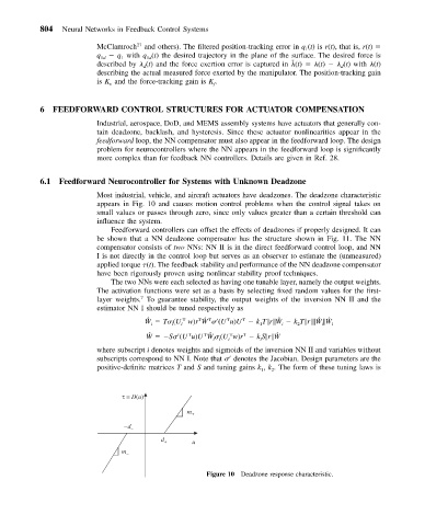
                          Most industrial, vehicle, and aircraft actuators have deadzones. The deadzone characteristic
                          appears in Fig. 10 and causes motion control problems when the control signal takes on
                          small values or passes through zero, since only values greater than a certain threshold can
                          influence the system.
                             Feedforward controllers can offset the effects of deadzones if properly designed. It can
                          be shown that a NN deadzone compensator has the structure shown in Fig. 11. The NN
                          compensator consists of two NNs: NN II is in the direct feedforward control loop, and NN
                          I is not directly in the control loop but serves as an observer to estimate the (unmeasured)
                          applied torque  (t). The feedback stability and performance of the NN deadzone compensator
                          have been rigorously proven using nonlinear stability proof techniques.
                             The two NNs were each selected as having one tunable layer, namely the output weights.
                          The activation functions were set as a basis by selecting fixed random values for the first-
                          layer weights. To guarantee stability, the output weights of the inversion NN II and the
                                     7
                          estimator NN I should be tuned respectively as
                                                   T ˆ
                                      ˆ
                                                                       ˆ
                                                                                  ˆ
                                                                                    ˆ
                                               T
                                                               T
                                      W   T  (Uw)rW   (Uu)U   kT r W   kT r  W  W    i
                                                      T
                                                           T
                                                                   1
                                       i
                                                                        i
                                                                            2
                                                                                   i
                                               i
                                             i
                                                                       ˆ
                                                     T ˆ
                                       ˆ
                                      W   S  (Uu)UW   (Uw)r   kS r W
                                                               T
                                                 T
                                                           T
                                                                   i
                                                       ii
                                                           i
                          where subscript i denotes weights and sigmoids of the inversion NN II and variables without
                          subscripts correspond to NN I. Note that    denotes the Jacobian. Design parameters are the
                          positive-definite matrices T and S and tuning gains k , k . The form of these tuning laws is
                                                                      2
                                                                   1
                                τ = D(u)
                                                m +
                                –d –
                                          d +
                                                  u
                                m –
                                                     Figure 10 Deadzone response characteristic.
   808   809   810   811   812   813   814   815   816   817   818