
Page 186 - Mechanics Analysis Composite Materials
P. 186
Chapter 4. Mechanics of’a composite layer 171
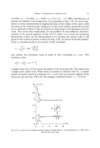
5.6 GPa, Gz3 = 6.4 GPa, vi3 = 0.095, ~23= 0.35, 5; = 25.5 MPa. Distributions of
stresses normalized to the acting stress G are presented in Fig. 4.38. As can be seen,
there is a stress concentration in longitudinal plies in the vicinity of the crack, while
the stress in the transverse ply, being zero on the crack surface, practically reaches
CT: at a distance of about 4mm (or about two thicknesses of the laminate) from the
crack. The curves look traditionally for the problem of stress diffusion. However,
analysis of the second equation of Eqs. (4.1 17) allows us to reveal an interesting
phenomenon which can be demonstrated if we increase the vertical scale of the
graph in the vicinity of points A and B (see Fig. 4.38). As follows from this analysis,
stress 0.~2 becomes equal to 0; at point A with coordinate
and reaches the maximum value at point B with coordinate xg = n/k?. This
maximum value
is higher than stress a’!that causes the failure of the transverse ply. This means that
a single crack cannot kxist. When stress CT; reaches its ultimate value a:, a regular
system of cracks located at a distance of 1, = n/k2 from one another appears in the
transverse ply (see Fig. 4.39). For the example considered above, I, = 12.8 mm.
“P
0;fl
-
1.5 r‘B’-.
1-