
Page 187 - Mechanics Analysis Composite Materials
P. 187
172 Mechanics and analysis of composite materials
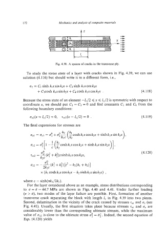
Fig. 4.39. A system of cracks in the transverse ply.
To study the stress state of a layer with cracks shown in Fig. 4.39, we can use
solution (4.116) but should write it in a different form, i.e.,
tn = CIsinh klx sin k2x + C2 sinh klxcos k2x
+ C3cosh klxsin k2x + C4 cosh klxcosk2x . (4.118)
Because the stress state of an element -Z42 <x < 142 is symmetricwith respect to
coordinate x, we should put C2 = C3 = 0 and find constants CI and C4 from the
following boundary conditions:
4x ZJ2) = 0, 4 x = ZC/2)= 0 . (4.119)
=
The final expressions for stresses are
4
zxz2 =-(e+g)zsinhklx cos k2x, (4.120)
k2c
x (kl cosh klxcos k2x - k2 sinh klx sin k2x) ,
where c = sinh(xkl/2k2).
For the layer considered above as an example, stress distributions corresponding
to 0 = 5 = 44.7 MPa are shown in Figs. 4.40 and 4.41. Under further loading
(0 > a), two modes of the layer failure are possible. First, formation of another
transverse crack separating the block with length ICin Fig. 4.39 into two pieces.
Second, delamination in the vicinity of the crack caused by stresses z,, and az(see
Fig. 4.41). Usually, the first situation takes place because stresses z,, and 0, are
considerably lower than the corresponding ultimate stresses, while the maximum
value of ax2 is close to the ultimate stress 0; = a:. Indeed, the second equation of
Eqs. (4.120) yields