
Page 192 - Mechanics Analysis Composite Materials
P. 192
Chapter 4. Mechanics of u composite luyer I71
lines with straight segments and kinks corresponding to degradation of particular
plies.
The foregoing procedure was described for a cross-ply layer consisting of plies
with different properties. For the layer made of one and the same material, there are
only three stages of loading - first, before the plies degradation, second, after the
degradation of the longitudinal or the transverse ply only, and third, after the
degradation of all the plies.
As a numerical example, consider a carbon-epoxy cylindrical pressure vessel
consisting of axial plies with total thickness ho and circumferential plies with total
thickness h90. The vessel has the following parameters: radius R = 500 mm, total
thickness of the wall h = 7.5 mm, ho = 2.5 mm, h90 = 5 mm. Mechanical charac-
teristics of a carbon-epoxy unidirectional ply are El = 140 GPa, E2 = 11 GPa,
v12 = 0.0212, v21 = 0.27, 8; = 2000 MPa, 8; = 50 MPa. Axial, ox, and circumfe-
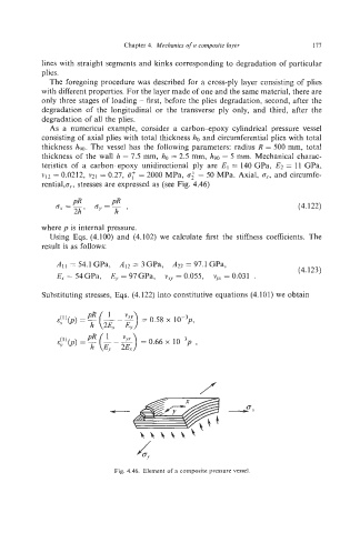
rentialp,,, stresses are expressed as (see Fig. 4.46)
(4.122)
where p is internal pressure.
Using Eqs. (4.100) and (4.102) we calculate first the stiffness coefficients. The
result is as follows:
All = 54.1 GPa, A12 = 3GPa, ,422 = 97.1 GPa, (4.123)
E, = 54GPa, Ey = 97GPa, v.,. = 0.055, v, = 0.031 .
Substituting stresses, Eqs. (4.122) into constitutive equations (4.101) we obtain
Fig. 4.46. Element of a composite pressure vessel.