
Page 190 - Mechanics Analysis Composite Materials
P. 190
Chapter 4. Mechanics of a composite layer 175
0 0.2 0.4 0.6 0.8
Fig. 4.43. Stress-strain diagram for a transverse ply.
strain diagram of the cross-ply layer corresponding to this model is shown in
Fig. 4.42 with a broken line.
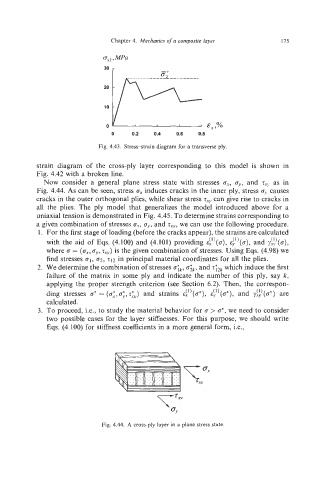
Now consider a general plane stress state with stresses c.~,T,,, and rIJ as in
Fig. 4.44. As can be seen, stress induces cracks in the inner ply, stress o, causes
cracks in the outer orthogonal plies, while shear stress T.~~can give rise to cracks in
all the plies. The ply model that generalizes the model introduced above for a
uniaxial tension is demonstrated in Fig. 4.45. To determine strains corresponding to
a given combination of stresses or,o!, and G,,,, we can use the following procedure.
1. For the first stage of loading (before the cracks appear), the strains are calculated
with the aid of Eqs. (4.100) and (4.101) providing &:')(a), &-!!)(a), and y!&)(o),
where o = (ox,t~-,~T~?)is the given combination of stresses. Using Eqs. (4.98) we
find stresses 01, 62. 212 in principal material coordinates for all the plies.
2. We determine the combination of stresses o;~,o:k,and z;~~which induce the first
failure of the matrix in some ply and indicate the number of this ply, say k,
applying the proper strength criterion (see Section 6.2). Then, the correspon-
(1)
(1)
(1)
ding stresses o*= (o;,o;,l~-:y) and strains zx (o*),cy (cr*), and ya (o*)are
calculated.
3. To proceed, i.e., to study the material behavior for rr > c*,we need to consider
two possible cases for the layer stiffnesses. For this purpose, we should write
Eqs. (4.100) for stiffness coefficients in a more general form, i.e.,
Fig. 4.44. A cross-ply layer in a plane stress state.