
Page 160 - Mechanics of Microelectromechanical Systems
P. 160
3. Microsuspensions 147
for It can be seen that the stiffness ratio is almost constant and equal
to 1, which indicates that the shearing effects are not particularly large.
Figure 3.15 Stiffness ratio in terms of and
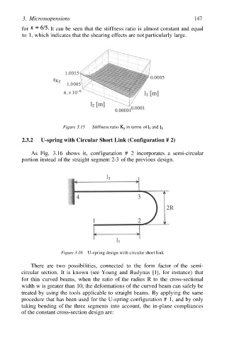
2.3.2 U-spring with Circular Short Link (Configuration # 2)
As Fig. 3.16 shows it, configuration # 2 incorporates a semi-circular
portion instead of the straight segment 2-3 of the previous design.
Figure 3.16 U-spring design with circular short link
There are two possibilities, connected to the form factor of the semi-
circular section. It is known (see Young and Budynas [1], for instance) that
for thin curved beams, when the ratio of the radius R to the cross-sectional
width w is greater than 10, the deformations of the curved beam can safely be
treated by using the tools applicable to straight beams. By applying the same
procedure that has been used for the U-spring configuration # 1, and by only
taking bending of the three segments into account, the in-plane compliances
of the constant cross-section design are: