
Page 156 - Mechanics of Microelectromechanical Systems
P. 156
3. Microsuspensions 143
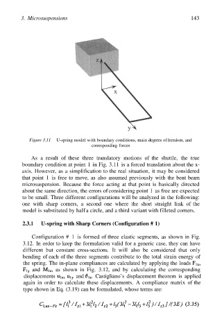
Figure 3.11 U-spring model with boundary conditions, main degrees of freedom, and
corresponding forces
As a result of these three translatory motions of the shuttle, the true
boundary condition at point 1 in Fig. 3.11 is a forced translation about the x-
axis. However, as a simplification to the real situation, it may be considered
that point 1 is free to move, as also assumed previously with the bent beam
microsuspension. Because the force acting at that point is basically directed
about the same direction, the errors of considering point 1 as free are expected
to be small. Three different configurations will be analyzed in the following:
one with sharp corners, a second one where the short straight link of the
model is substituted by half a circle, and a third variant with filleted corners.
2.3.1 U-spring with Sharp Corners (Configuration # 1)
Configuration # 1 is formed of three elastic segments, as shown in Fig.
3.12. In order to keep the formulation valid for a generic case, they can have
different but constant cross-sections. It will also be considered that only
bending of each of the three segments contribute to the total strain energy of
the spring. The in-plane compliances are calculated by applying the loads
and as shown in Fig. 3.12, and by calculating the corresponding
displacements and Castigliano’s displacement theorem is applied
again in order to calculate these displacements. A compliance matrix of the
type shown in Eq. (3.19) can be formulated, whose terms are: