
Page 151 - Mechanics of Microelectromechanical Systems
P. 151
138 Chapter 3
stiffnesses by utilizing the matrix transformation of Eq. (3.4), and the
stiffness becomes:
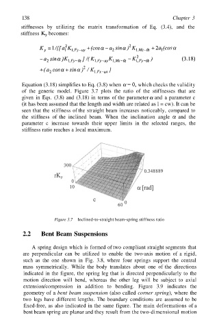
Equation (3.18) simplifies to Eq. (3.8) when which checks the validity
of the generic model. Figure 3.7 plots the ratio of the stiffnesses that are
given in Eqs. (3.8) and (3.18) in terms of the parameter and a parameter c
(it has been assumed that the length and width are related as l = cw). It can be
seen that the stiffness of the straight beam increases noticeably, compared to
the stiffness of the inclined beam. When the inclination angle and the
parameter c increase towards their upper limits in the selected ranges, the
stiffness ratio reaches a local maximum.
Figure 3.7 Inclined-to-straight beam-spring stiffness ratio
2.2 Bent Beam Suspensions
A spring design which is formed of two compliant straight segments that
are perpendicular can be utilized to enable the two-axis motion of a rigid,
such as the one shown in Fig. 3.8, where four springs support the central
mass symmetrically. While the body translates about one of the directions
indicated in the figure, the spring leg that is directed perpendicularly to the
motion direction will bend, whereas the other leg will be subject to axial
extension/compression in addition to bending. Figure 3.9 indicates the
geometry of a bent beam suspension (also called corner spring), where the
two legs have different lengths. The boundary conditions are assumed to be
fixed-free, as also indicated in the same figure. The main deformations of a
bent beam spring are planar and they result from the two-dimensional motion