
Page 84 - Mechatronic Systems Modelling and Simulation with HDLs
P. 84
4.5 MODELLING PARADIGMS 73
Hardware description 4.7. This corresponds with the first step in the direction of
implementation. Most synthesis tools are able to translate this description into a
gate circuit, which could be followed up by representation on a FPGA.
LIBRARY IEEE;
USE IEEE.std_logic_1164.all; -- IEEE package for logic types
USE IEEE.std_logic_arith.all; -- IEEE package for associated
arith.
ENTITY multiplier IS
PORT(clk: in std logic;
a, b : IN std_logic_vector(3 DOWNTO 0);
q : OUT std_logic_vector(7 DOWNTO 0));
END multiplier;
ARCHITECTURE behaviour1 OF multiplier IS
BEGIN PROCESS
BEGIN
WAIT UNTIL rising_edge(clk); -- Wait for rising edge
q <= a*b; -- Multiplier and assign result to
END PROCESS;
END behaviour1;
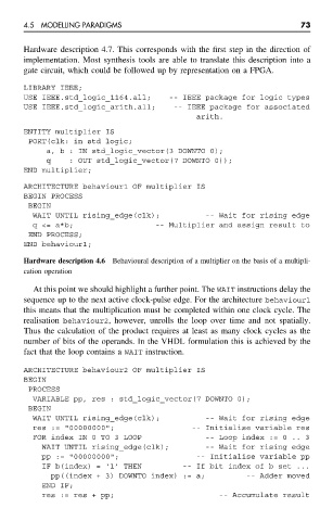
Hardware description 4.6 Behavioural description of a multiplier on the basis of a multipli-
cation operation
At this point we should highlight a further point. The WAIT instructions delay the
sequence up to the next active clock-pulse edge. For the architecture behaviour1
this means that the multiplication must be completed within one clock cycle. The
realisation behaviour2, however, unrolls the loop over time and not spatially.
Thus the calculation of the product requires at least as many clock cycles as the
number of bits of the operands. In the VHDL formulation this is achieved by the
fact that the loop contains a WAIT instruction.
ARCHITECTURE behaviour2 OF multiplier IS
BEGIN
PROCESS
VARIABLE pp, res : std_logic_vector(7 DOWNTO 0);
BEGIN
WAIT UNTIL rising_edge(clk); -- Wait for rising edge
res := "00000000"; -- Initialise variable res
FOR index IN 0 TO 3 LOOP -- Loop index := 0 .. 3
WAIT UNTIL rising_edge(clk); -- Wait for rising edge
pp := "00000000"; -- Initialise variable pp
IF b(index) = ‘1’ THEN -- If bit index of b set ...
pp((index + 3) DOWNTO index) := a; -- Adder moved
END IF;
res := res + pp; -- Accumulate result