
Page 87 - Mechatronic Systems Modelling and Simulation with HDLs
P. 87
76 4 MODELLING IN HARDWARE DESCRIPTION LANGUAGES
Now, if analogous behaviour is to be formulated in a hardware description
language this normally occurs in the form of mathematical equations. In VHDL-
AMS these equations are also termed simultaneous instructions. Both sides of the
equation must have real values. The equations are symmetrical in the sense that
swapping the left and right-hand side leads to the same results. The analogue
solver is responsible for the fact that these equations are approximately fulfilled.
In addition to the equations there are also the simultaneous versions of the IF,
CASE and PROCEDURAL instructions, which facilitates sequential notation. Let us
now clarify this using the example of a diode model.
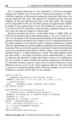
Hardware description 4.8 shows a simple diode model in VHDL-AMS, see
[160]. The division into interface and implementation, i.e. into ENTITY and ARCHI-
TECTURE, also applies for the analogue model. In addition to the anode and cathode
electrical connections the interface now includes a GENERIC instruction that permits
the named parameter to set when the model is instanced. Furthermore, standard
values are specified that are used if no further specifications are encountered during
instancing. Then some electrical quantities are initially declared in the architecture
such as, for example, the diode current id and the voltage ud across the diode. The
threshold voltage ut is finally declared as a constant. The actual equations define
the diode current id, the charge of the diode q and an additional current ic, which
is found from the derivative of charge with respect to time q’DOT. Furthermore,
the fact is worthy of special mention that individual equations can be allocated
to a predefined accuracy group by means of the TOLERANCE instruction, so that
different accuracies can be set for various equations. However, this means that
no decision is anticipated regarding which criteria the simulator is to use for the
evaluation of accuracy and how this is to be calculated.
ENTITY diode IS
-- Parameter declaration with default values ...
GENERIC (is0:real := 1.0e-14; tau, rd : real := 0.0);
-- Inputs/outputs
PORT (TERMINAL anode, cathode: electrical);
END ENTITY diode;
ARCHITECTURE simultaneous OF diode IS
-- Declaration of variables and constants ...
QUANTITY ud ACROSS id, ic THROUGH anode TO cathode;
QUANTITY q: real;
CONSTANT ut: voltage := 0.0258;
BEGIN -- Defining equations ...
id == is0*(exp((ud-rd*id)/ut)-1.0);
q == tau*id TOLERANCE "Charge";
ic == q’DOT;
END ARCHITECTURE simultaneous;
Hardware description 4.8 Simultaneous behavioural description of a diode