
Page 82 - Mechatronic Systems Modelling and Simulation with HDLs
P. 82
4.5 MODELLING PARADIGMS 71
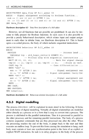
ARCHITECTURE data_flow OF full_adder IS
BEGIN -- Signal assignment according to Boolean function...
sum <= i1 xor i2 xor ci AFTER 3 ns;
co <= (i1 and i2) or (i1 and ci) or (i2 and ci) AFTER 2 ns;
END data_flow;
Hardware description 4.3 Data flow description of a full adder
However, not all functions that are possible are predefined. It can also be tire-
some to fully prepare the Boolean functions. In such cases it is also possible to
provide a purely behavioural description, which relates input and output assign-
ment to each other in tabular form, see Hardware description 4.4. This is based
upon a so-called process, the body of which includes sequential instructions.
ARCHITECTURE behaviour OF full_adder IS
BEGIN
PROCESS -- Process head ...
VARIABLE tmp : std_logic_vector(2 DOWNTO 0);
BEGIN -- Process body with sequential instructions ...
WAIT ON i1, i2, ci; -- Wait for signal change
tmp(2) := i1; tmp(1) := i2; tmp(0) := ci; --Store in vect.
CASE tmp IS -- Case differentiation ...
WHEN "000" =>
sum <= ‘0’ AFTER 3 ns; -- Signal assignment sum
co <= ‘0’ AFTER 2 ns; -- Signal assignment Carry-Out
WHEN "001" =>
sum <= ‘1’ AFTER 3 ns; -- Signal assignment sum
co <= ‘0’ AFTER 2 ns; -- Signal assignment Carry-Out
WHEN ...
END CASE;
END PROCESS;
END behaviour;
Hardware description 4.4 Behaviour-oriented description of a full adder
4.5.3 Digital modelling
The process (PROCESS) will be explained in more detail in the following. It forms
the work-horse of digital modelling. Virtually all digital relationships are modelled
either directly as a process or in a form that is easy to convert into a process. The
process is attributed to the parallel instructions. Thus it is processed in parallel to
the other processes and the remaining parallel instructions. The body of a process
contains sequential commands that are thus processed one after the other. When
the processing reaches the end of the body, it jumps back to the start and thus
executes an endless loop. To prevent this from causing the simulation to hang, each
body must contain at least one synchronisation point in the form of an explicit or
implicit WAIT instruction. Its task is to delay progress in the body of the process